Hardware
w-iLab.1 Hardware
This testbed is currently under development, so check back here regularly for updates.
The w-iLab.1 testbed is split into two entities:
- 44 testbed nodes are mounted to the ceiling of the datacenter of the iGent building (in Ghent): a 30m by 10m room in a grid configuration with dx = 2.5 meter and dy = 2 meter. The 44 installed nodes can be seen on the inventory.
- IoT Officelab : 110 testbed nodes installed on three floors in the iGent building.
Inventory
The inventory is located at http://boss.wilab1.ilabt.iminds.be/inventory . This tool can help you find out the exact location of the nodes and their configuration.
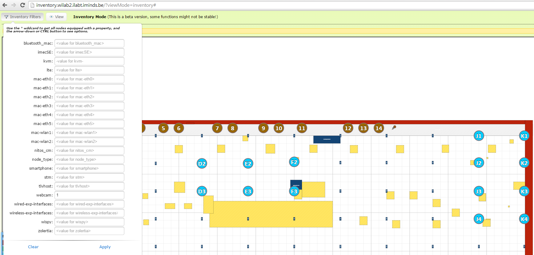
You can use the filter function to look for nodes with specific extensions (e.g. with webcams, with WiSpy, with a certain WiFi mac address).
Node configuration
The w-iLab.1 testbed consists mainly of Intel NUC devices with the following specs:
| Feature | NUC D54250WYKH |
|---|---|
| CPU type | Intel Core i5-4250U Processor (3M Cache, up to 2.60 GHz) |
| RAM (GB) | 8GB DDR3 1600MHz |
| Hard disk | 320GB (2.5”, SATA 6Gb/s, 7200RPM, 16MB) |
| WiFi | 1x802.11abgn+BT, 1x802.11ac |
| Sensor node | Yepkit USB hub + Zolertia Re-Mote |
| Bluetooth | Bluetooth 4.0 LE/3.0 HS/2.1 EDR (on 802.11n WiFi card) |
- Naming convention:
- nucX-Y
- X = floor of iGent building, Y = NUC numbering per floor
- Details on the 802.11abgn+BT interfaces:
- Sparklan WPEA-251N(BT) mini PCIe 2T2R chipset: AR9462 , AR5B22
- To each Wi-Fi card, two antennas are connected (2x2 MIMO is supported).
- Supports also Bluetooth 4.0 LE/ 3.0 HS/ 2.1 EDR standard
- Recommended driver: ath9k
- Details on the 802.11ac Wifi interfaces (second WiFi card):
- Compex WLE900VX / 802.11ac/n/b/g 3x3 MIMO / PCI-Express Full-Size MiniCard: Qualcomm Atheros QCA9880
- To each Wi-Fi card, three antennas are connected (3x3 MIMO is supported).
- Recommended driver: ath10k
- Power control of the NUC nodes is done using Power-Over-Ethernet.
Some nodes have extra USB extensions, like sensor nodes. Use the inventory to look for specific devices.
Yepkit USB Switchable hub
The extra USB extensions can be switched on and off with the Yepkit USB Swichable hub through which they are connected to the NUC. This is useful to powercycle or enable/disable sensors.
To control the Yepkit USB ports:
# change to shared directory where ykushcmd is present (git at: https://github.com/Yepkit/ykush/tree/master/ykushcmd)
# check if a USB Hub is present
ykushcmd ykush3 -l
# bring up port 1
ykushcmd ykush3 -u 1
# bring down port 1
ykushcmd ykush3 -d 1
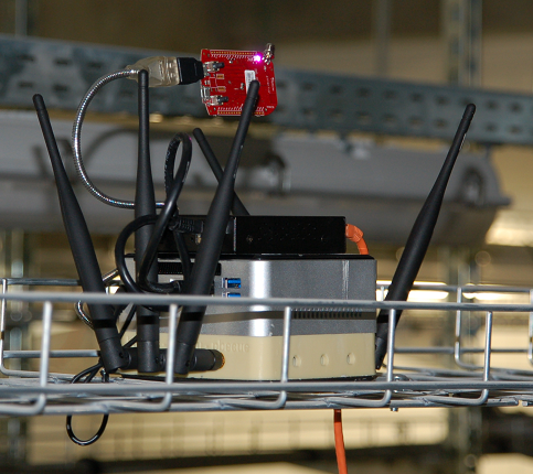
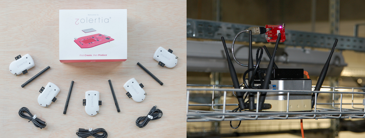
Zolertia Re-Mote Sensor
Some nodes are equipped with one or more Zolertia Re-Mote sensor nodes. The RE-Mote is based on the CC2538 ARM Cortex-M3 with a robust 2.4Ghz IEEE 802.15.4 radio, running up to 32MHz with 512KB of programable flash and 32KB of RAM, bundled with a CC1200 868/915Mhz RF transceiver. The RE-mote features a built-in TMP102 temperature sensor, microSD over SPI, battery charger and management (BQ24075) with an input range of 2 to 26VDC.
More info can be found here: http://zolertia.io/product/hardware/re-mote
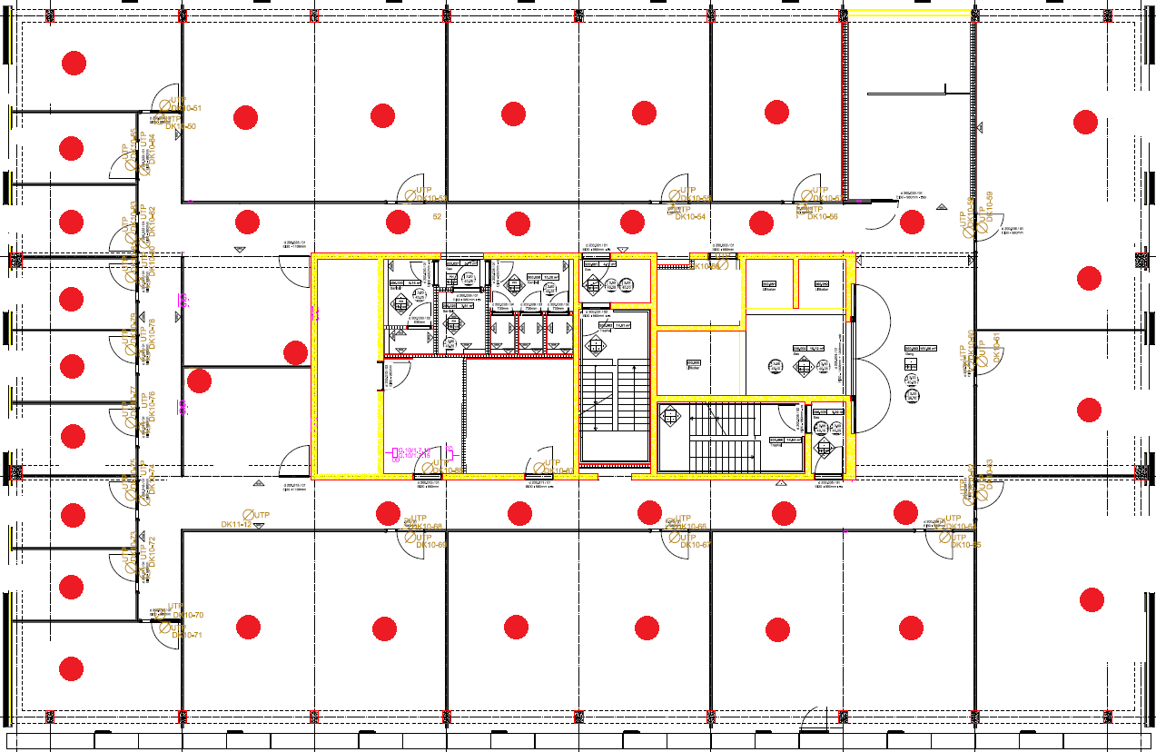
Officelab

In the iGent building, three floors of the building are transformed into a real-life office lab environment (floor 9-10-11). Wireless and wired sensor technology will be deployed to demonstrate tomorrow’s smart office applications optimizing work spaces, visitor’s experiences, workers’ comfort, etc. In total, 120 nodes will be deployed.
Example floor plan for floor 10. Red dots represent node locations.
w-iLab.2 Hardware
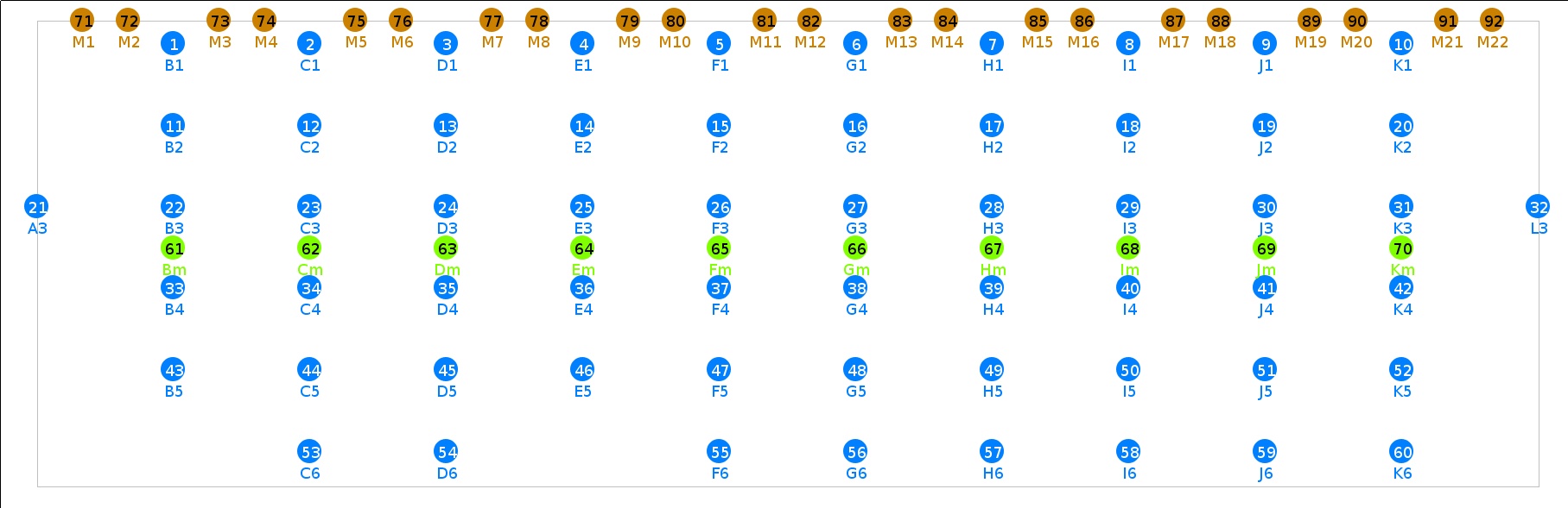
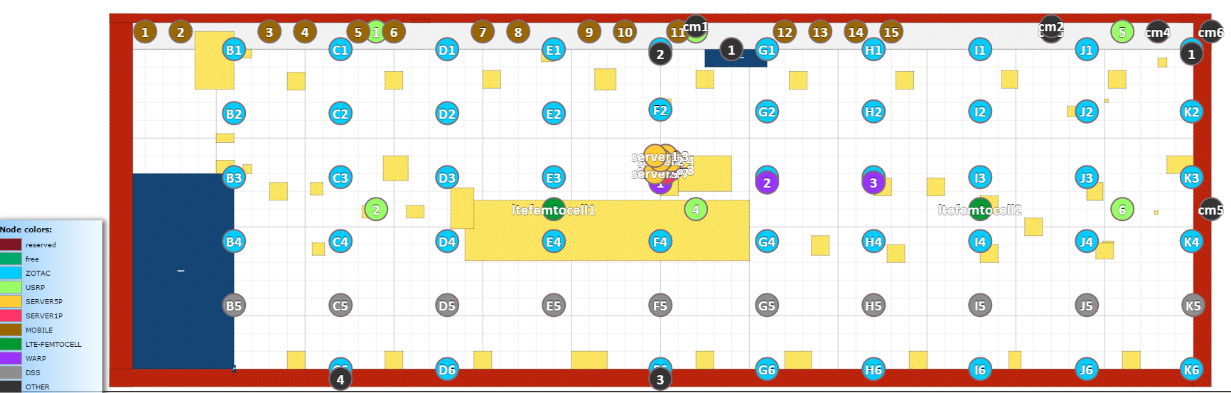
Map
The nodes in the testbed are mounted in 66m by 20.5m open room in a grid configuration with dx = 6 meter and dy = 3.6 meter. The 60 installed nodes are represented by the blue locations on the picture. The testbed has been extended with 40 extra wireless nodes of type APU. These can be seen on the inventory. In total, 100 fixed wireless nodes are available and 16 mobile robots. The green and orange locations are used to show the mobile nodes, the SDRs (USRP, WARP,…), the LTE femto cells, the IP cameras and many other types of wireless hardware.
Inventory
The inventory is located at http://inventory.wilab2.ilabt.imec.be . This tool can help you find out the exact location of the nodes and their configuration. The page also offers some filters to make it easier to search for suitable nodes for your experiment.
Different colors represent different node types.
Node configuration
The w-iLab.2 testbed has 7 different node types where the experimenter can deploy an operating system of choice:
- ZOTAC : 48 wireless nodes (zotacXY)
- APU : 40 wireless nodes with 2 Gigabit experimental network interfaces (apuXY)
- DSS : 10 wireless nodes (dssXY)
- MOBILE : 15 mobile wireless nodes (mobile1 to mobile15)
- SERVER5P : 6 servers with 5 experimental network interfaces (server1 to server6)
- SERVER1P : 2 servers with 1 experimental network interface (server7 and server8)
- SERVER1G2X : 7 servers with 2 10G experimental network interfaces (server9 to server15)
X = column letter, Y = row number
| Feature | ZOTAC | APU 1d4 | DSS/MOBILE | SERVER1P/SERVER5P | SERVER1G2X |
|---|---|---|---|---|---|
| CPU type | Intel Atom D525 (2cores, 1.8GHz) | AMD G series T40E APU (2cores, 1GHz) | Intel core i5 | 8x dual Intel Xeon Processor 5600 Series | Intel Xeon Processor D-1541 (2.1GHz, 8 cores, 16 threads) |
| RAM (GB) | 4GB DDR2 800MHz PC2-6400 CL6 | 4GB DDR3 1066MHz | 4GB DDR2 800MHz PC2-6400 CL6 | 12GB DDR2 800MHz PC2-6400 CL6 | 16GB DDR4 2133MHz |
| Hard disk | 160GB (2.5”, SATA, 7200RPM, 16MB) | 32GB (SSD,mSATA) | 60GB (2.5”, SATA, SSD) | 160GB (2.5”, SATA, 7200RPM, 16MB) | 500GB (3.5”, SATA, 7200RPM, 64MB) |
| WiFi | 2x802.11abgn | 2x802.11ac | 1x802.11abgn, 1x802.11ac | No WiFi cards/dongles | No WiFi cards/dongles |
| Sensor node | EE + RM090 | Zolertia Re-Mote | EE + RM090 | No EE/sensor node | No EE/sensor node |
| Bluetooth | USB 2.0 Bluetooth (Micro CI2-v3.0 EDR) | No Bluetooth | USB 2.0 Bluetooth (Micro CI2-v3.0 EDR) | No Bluetooth | No Bluetooth |
- Details on the 802.11abgn Wifi interfaces:
- Sparklan WPEA-110N/E/11n mini PCIe 2T2R chipset: AR9280
- To each Wi-Fi card, two antennas are connected (2x2 MIMO is supported).
- 2 x 2 Attenuator 20 dB (one attenuator between each Wi-Fi output and each antenna):
- Telegärtner J01156R0041; R-SMA (m-f) 0-6GHz 50Ohm 2W
- Recommended driver: ath9k
- Details on the 802.11ac Wifi interfaces (second WiFi card on DSS and MOBILE nodes):
- Compex WLE900VX / 802.11ac/n/b/g 3x3 MIMO / PCI-Express Full-Size MiniCard: Qualcomm Atheros QCA9880
- To each Wi-Fi card, three antennas are connected (3x3 MIMO is supported).
- Recommended driver: ath10k
- Power control of the ZOTAC and DSS nodes is done using Racktivity RC0816 Power Distribution Units (PDU).
Some nodes have extra USB extensions, like cognitive radio devices. Use the inventory to look for specific devices.
Other devices are only accessible over the experiment network and can thus only be accessed by swapping in a device with an experiment network interface (SERVER1P, SERVER5P, SERVER1G2X, DSS). These devices are:
- USRP devices
- 6x USRP N210 with XCVR 2450 daughter boards
- 2x USRP X310 with UBX160 daughter boards
- 4x USRP B210
- 4x USRP B200
- WARP devices
- 3x WARPv2
- ZYNQ devices
- 3x zc706zynqSDR
- 2x zedzynqSDR
ALIX devices (devices with 500MHz CPU, 256MB RAM, 4G compact flash card, Broadcom wireless chipset, see the tutorial below)
RM090 Sensor node specs
The RM090 sensor node is a joint design by Rmoni and iMinds. The major reason for iMinds to create a new sensor node was of the lack of sufficient resources on the TMote Sky (see table). Especially the 48k of flash on the TMote was the enabler to upgrade the testbed.
| Feature | Imote (2003) | Mica2 (2003) | MicaZ (2004) | Telos (2005) | IBBT-Rmoni RM090 (2010) |
|---|---|---|---|---|---|
| CPU type @[MHz] | 32bit ARM @12 | 8bit Atmel @8 | 8bit Atmel @8 | 16bit TI @8 | 16bit TI @18MHz |
| SRAM [kB] | 64 | 4 | 4 | 10 | 16 |
| FLASH [kB] | 512 | 128 + 512 | 128 + 512 | 48 KB / 1024 KB | 256 KB/128 KB + 16KB eeprom |
| Radio | BT | 300-900MHz | 802.15.4 | 802.15.4 | 802.15.4 2.4GHz band |
| Bandwidth [kb/s] | 720 | 15 | 250 | 250 | 250 |
| Carrier Sense/ Rx/Tx Current [mA] | 15 / 24 / 24 | 08/10/27 | 08/20/18 | 01/20/18 | 18.5 /18.5 / 33.6 @ 4dBm
25.8 @ 0dBm
|
| sleep current [uA] | 01/01/50 | 19 | 27 | 6 | 2 |
| OS support | TinyOS | TinyOS | TinyOS | TinyOS | TinyOS or IDRA |
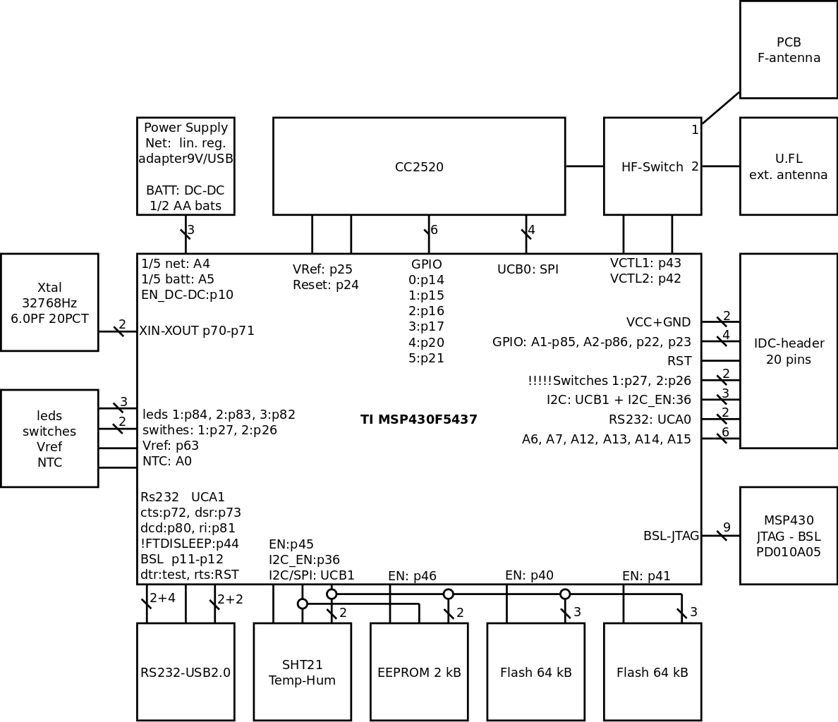
We tried to be as compliant as possible with the TMote Sky with the second generation chips of TI the msp430f5437 and the CC2520. The IDC headers, the 3 leds, the USB interface are as much compliant as possible.
Here you can find a block diagram of the RM090:
Environment emulator
The Environment Emulator (EnvEmu, or EE) is located in between the embedded PC and the RM090 (or Zolertia) sensor nodes. It opens up a lot of real-life test cases, of which the major ones are described below:
- The EE can disconnect the USB power from the DUT, and power it with its own regulating voltage source. This enables the EE to emulate the real behavior of a battery depleting, energy harvesting power sources, failing of the mote, …
- The current used by the DUT can be measured with a sample frequency of 10kHz. Using this approach, it is very easy to determine the exact power consumption when it is running the current application, protocol, …
- The EE has some General Purpose digital Input / Output pins connected to the DUT. This allows for real-life, real-time digital sensor / actuator emulation. These pins can also be used to tag specific states generated by the DUT to ease the analysis and classification of the power consumption.
- Some analogue input/output pins are also connected to the DUT, making the emulation of real-life, real-time analogue sensors/actuators possible.
- Audio input/output signals can be injected and extracted from the embedded PC to the DUT making all sorts of audio over sensor network experiments very easy to conduct.
- The EE can be used as an energy harvester.The EE can disconnect the USB power of the device under test (DUT) and can alternatively power the DUT via its battery interface with a variable voltage supply. By measuring the current at a high sample rate and use this information to control the voltage supply we can build a controlled loop feedback mechanism. To emulate the real behavior of an energy harvester we implemented the law of Coulomb as a feedback mechanism. Furthermore as we are at all times aware of the consumed current by the DUT (sample rate of 4 kHz) and the tuned voltage we can determine the exact power consumption (more details below).
All of this can be prepared before running an experiment or can be adjusted real time during the experiment by using an OMF experiment description.
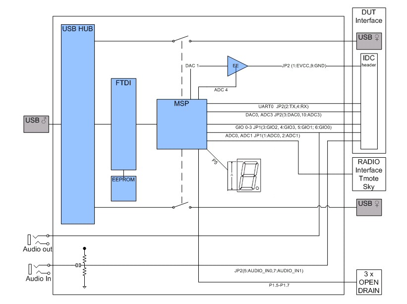
If you take a closer look to the block diagram of the EnvEmu you will notice that is based on TMote Sky. We stripped down the TMote Sky by removing the sensors, leds, buttons, radio, I2C msp flash lock circuit and also flash. So basically we stripped it down to ftdi, msp430, IDC header and radio interface. We added a 3ports USB hub, 2 USB switches that are connected to slave female USB connectors, 7 segment display, battery emulator and audio jacks. See the block diagram below.
Both the front an the back view of the board can be found here:
Here you can find the detailed electronic circuit of the battery emulator.
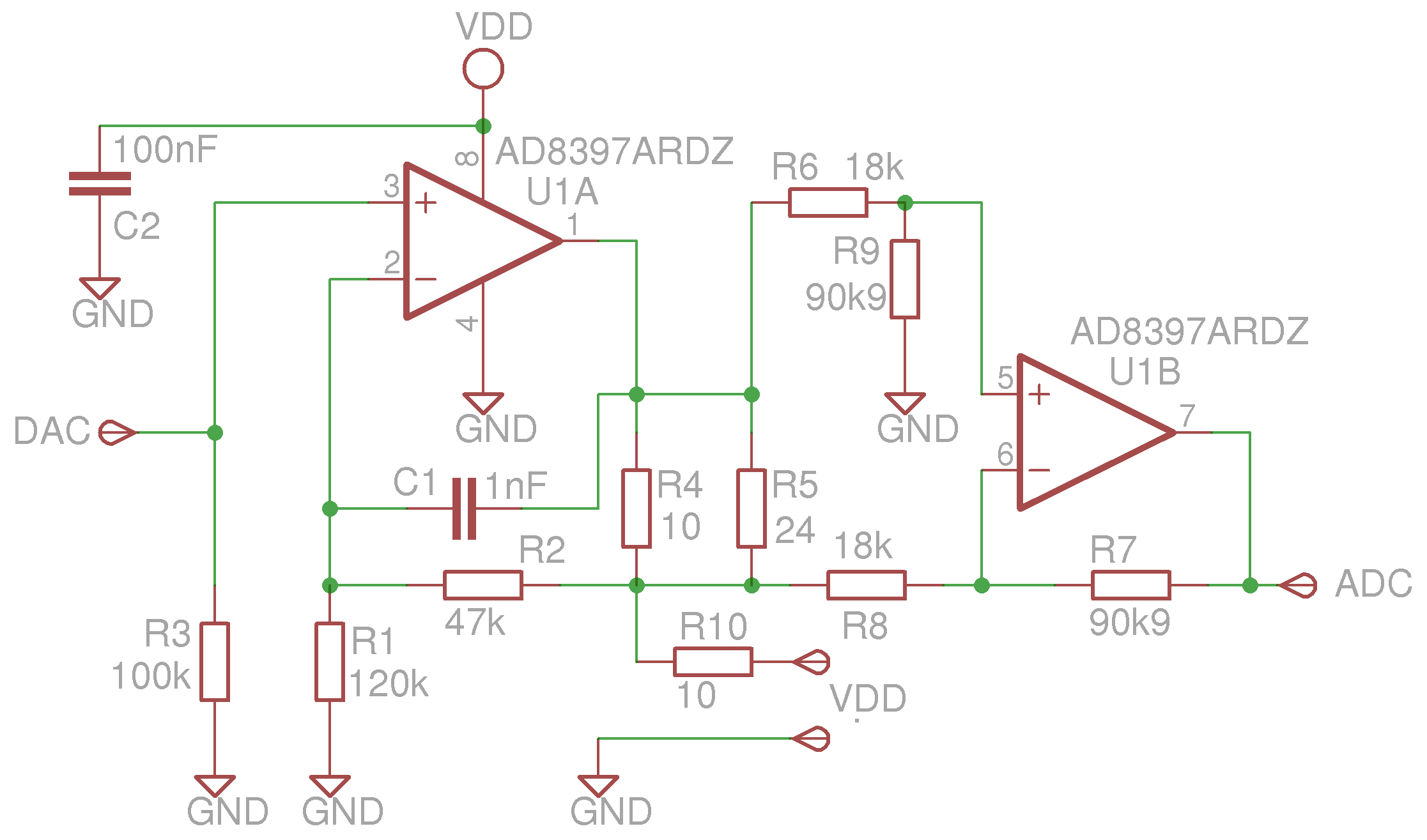
The electronic diagram can be downloaded here: Environment Emulator Electronics Schema.
A new sensor board was created, which is basically a stripped version of the TMote Sky and we called it the Environment Emulator (EE).
On the EE we connected VDD (schematic) to the USB power of the board. The ADC and DAC lines (schematic) are connected to DAC1 and ADC4 of an MSP430. The DUT lines are then interfaced to the battery interface of the device under test. Implementing just the schematics as it is and connect it to an existing tmote or telosb gives the same functionality. The main component in the schematic is U1 which is a rail-to-rail, high output current amplifier. U1a is used to implement a voltage follower and maps the 2.5 V coming from the DAC (maximum output of DAC1 of the MSP430) to 3.5V (the maximum supply voltage of the DUT). Standard op amp schematics are not able to drive high capacitive loads . C1 and R10 were added in the second version of the EE and are used as inner and outer loop compensations for a better response when driving high capacitive loads. 10uF is a typical input capacitor of a sensor node and is much higher than what an opamp (typical 200pF) can drive without compensations. U1b is used to implement a differential amplifier and maps a current of 70mA trough R4 and R5 to 2.5V on the input of the ADC (the maximum input voltage of ADC4 of the MSP430). To implement the law of Coulomb a tinyos application was developed where we implemented an user event ‘stream’ with these parameters; start value which is the DAC value at t0, virtual capacitor and the harvester itself. When executed a continuous sampler will start on ADC4 with a interSampleDelay of 250us (or sample rate of 4kHz). On every sampler buffer done event the next Dac value will be calculated as follows (sampler buffer size is 50):
DacValue(t+1) = DacValue(t) + SUM ( harvester - samplerBuffer(t)[i] ) / virtualCapacitor.
The unit of the virtualCapacitor is 5uF and is derived from the interSampleDelay/numberOfSamplesPerBuffer.
The harverster engine will be activated when the capacitor is > 0. The unit of the capacitor is microFarad (uF). DAC1 is internally connected to ADC4. DAC0 is internally connected to ADC0. When activated the maximum sample rate of the ADC will be ceiled to 6kHz (because of serial speed limits)
When activated; for every sampler buffer the next Dac value will be calculated as follows:
DacValue(t+1) = DacValue(t) + SUM ( harvester - samplerBuffer(t)[i] ) / harvesterMulitiplier with harvesterMulitiplier = 5*10^-5 * harvestorCapacitor (uF) * ADCsampleRate (Hz) and can be derived from the electrical circuit (Thanks Ruben Catteeuw), see source code of EE for details Be carefull: the harvesterMulitiplier will be floored to 1! The charge of the capacitor is limited to 4095 x harvesterMulitiplier.
The electrical charge of this capacitor (uint44_t 32+12) is equal to DacValue multiplied by the harvesterMulitiplier. Both harvesterMulitiplier and harvesterCapacitor are of the type: uint32_t. Max value of the harvestorCapacitor is 4294967296uF or 4294F.
For example; for a battery emulation of 2.4V/2500mAh, we could define a full battery with initial voltage of value_0 = 2824 (2.400 V) and a harverster which is equal to zero and a capacitor of 3750 F (C=I*t/U) ( = 2500 *10^-3 * 60 * 60 / 2.4)
For example; for solar cell emulation, we could define a capacitor with initial voltage of value_0 = 0 (0.000 V) and a harverster which is equal to 1mA (59) and a capacitor of 470uF.So it will take 1.5s to charge the capacitor up to 3.3V without any load.
With a sampleRate of 6kHz you will get a reaction time of 4 samples x 167 us which makes 666 us with version 1.00 of the EE. Which is a lot faster than the 12.5 ms of the previous version of the EE v0.92a So be carefull with tranmisions of small frames and too small harvestorCapacitors before making conclusions. Info: frameTime= #bytes * 2 * 16us (ex. 10 bytes -> 320us) In order to keep the radio running the DAC voltage should never become lower then 1.8V. Suppose you can charge the capacitor up until 3.3V then voltage drop should never be bigger than 1.5V. With the law of Coulomb in our head; Q = CU = It. I will be around 20mA for RX/TX of the CC2X20, t is the total frameTime, U is in our example the maximum voltage drop of 1.5V. Then the frameTime will imply the minimum capacitance. Asume frameTime is 1ms and the harvester is 1mA (20mA->19mA) then C should be at least be 12.7uF. Best practive; take some margin as their will be some power consumption by the microcontroller and radio turn around times 2x 192us (ON/RX->TX->RX).
Some EE related publications:
- Moerman B. Jooris P. De Mil T. Allemeersch L. Tytgat P. Demeester, “WiLab: a large-scale real-life wireless test environment at IBBT”, published in Proceedings of DSP Valley seminar “Sensor driven state-of-the-art Mechatronics”, Anderlecht, Belgium, 20 February 2008
- Tytgat B. Jooris P. De Mil B. Latre I. Moerman P. Demeester, “Demo abstract: WiLab, a real-life wireless sensor testbed with environment emulation”, published in European conference on Wireless Sensor Networks, EWSN adjunct poster proceedings (EWSN), Cork, Ireland, 11-13 February 2009
- De Mil, B. Jooris, L. Tytgat, et al., “Design and Implementation of a Generic Energy-Harvesting Framework Applied to the Evaluation of a Large-Scale Electronic Shelf-Labeling Wireless Sensor Network,” EURASIP Journal on Wireless Communications and Networking, vol. 2010, Article ID 343690, 12 pages, 2010. doi:10.1155/2010/343690
Software-Defined Radio
A number of Software-Defined Radio (SDR) devices are available in the w-iLab.2 testbed. As with the other hardware and tools in w-iLab.2, it is up to the experimenters to decide how to use the hardware that is made available. Signals may only be transmitted in the ISM bands due to license restrictions.
Check out the inventory to see which SDR devices are installed and where.
USRP family
USRP N210
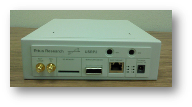
There are 6 USRP N210 N210 datasheet devices
installed in the w-iLab.2 testbed. The USRPs have 192.168.X0.2 as IP address, where X is the ID of USRP device within
the testbed, X=1..6
The USRP N210 are statically connected to 6 SERVER1G2X servers, you need to reserve the correct server to use a USRP, please refer to inventory for the exact mapping between servers and USRPs. The inventory page also allows remote power cycle of the USRP. The default image for SERVER1G2X has GNURadio version 3.7.9 and UHD_003.009.002 installed.
Same as for other types of devices, experiments using USRP can be swapped in via Emulab or jFed. For a jFed experiment, !!!! Do NOT draw any links in jFed for the USRPs. (Reserving and selecting in jFed is still needed) !!!!. For an emulab experiment, the USRP devices and servers have to be reserved on the reservation page before they can be used in an experiment.
USRP X310
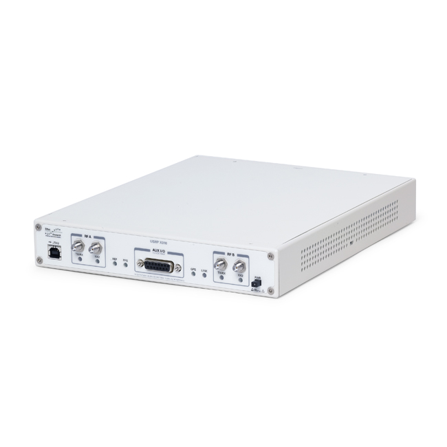
There are 2 USRP X310 x310 datasheet devices in the w-iLab.2 testbed,
denoted as USRPx310-1, USRPx310-2 respectively. The jtag USB interfaces are connected to the 2 APU nodes
(U2, V2) respectively. The 10G Ethernet interfaces are connected to a switch, which allows user to establish a VLAN
connection to the 10G interface of a SERVER1G2X. By default, USRP X310’s 10G interface has IP address 192.168.40.2/24.
And because there is a switch between USRP and the server, the experimenter needs to define a link in jFed accordingly
in order to reach the USRP X310, this is different for the usage of USRP N210.
USRP B200/B210
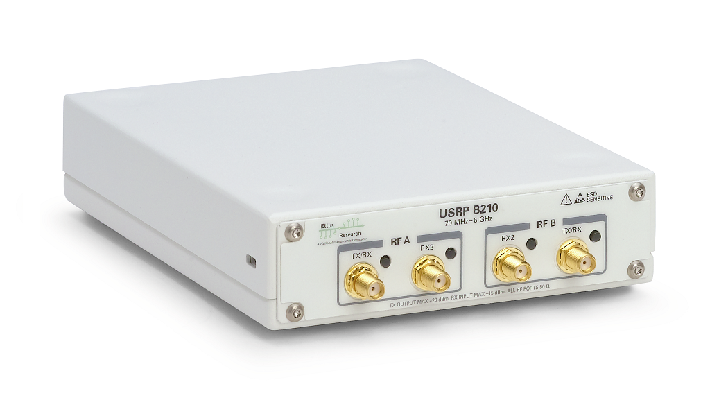
There are 4x USRP B200 and 4x USRP B210 devices installed in w-iLab.2 testbed. They are connected to specific nodes (Intel NUC) through USB3 connection, there is no other connections on these USRP.
ZYNQ family
Xilinx ZC706 and FMCOMMS2
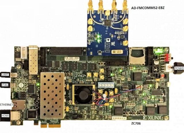
Three zc706 Zynq SDRs are deployed in w-iLab.t, which consist of a Xilinx ZC706 evaluation board and an FMCOMMS2 radio frontend.
All three boards are configured to boot via JTAG. Each board has 4 antenna ports, the antenna confiuration, UART, JTAG and Ethernet ports of the SDR boards are shown below.
- For zc706zynqSDR1:
- rx1: 2.4 GHz / 5 GHz dual band
- rx2: 900MHz
- tx1: 900MHz
- tx2: 2.4 GHz / 5 GHz dual band
- UART, JTAG: Server16
- Eth port: experiment switch, need to configure the link in jFed experiment to reach the board over Ethernet
- For zc706zynqSDR2:
- rx1: 2.4 GHz / 5 GHz dual band
- rx2: ALFA 2.4 GHz / 5 GHz dual-band patch directional antenna, pointing towards tx1 antenna of zcu102zynqSDR1
- tx1: connected to ad-trxboost1-ebz board <https://wiki.analog.com/resources/eval/user-guides/ad-trxboost1-ebz>, the board gives tx power boost of 18 dB, its output is connected to a 2.4 GHz / 5 GHz dual band antenna.
- tx2: 2.4 GHz / 5 GHz dual band
- UART, JTAG: apuV4
- Eth port: experiment switch, need to configure the link in jFed experiment to reach the board over Ethernet
- For zc706zynqSDR4:
- rx1: 2.4 GHz / 5 GHz dual band
- rx2: ALFA 2.4 GHz / 5 GHz dual-band patch directional antenna, pointing towards tx1 antenna of zcu102zynqSDR1
- tx1: connected to ad-trxboost1-ebz board <https://wiki.analog.com/resources/eval/user-guides/ad-trxboost1-ebz>, the board gives tx power boost of 18 dB, its output is connected to a 2.4 GHz / 5 GHz dual band antenna.
- tx2: 2.4 GHz / 5 GHz dual band
- UART, JTAG: apuU4
- Eth port: experiment switch, need to configure the link in jFed experiment to reach the board over Ethernet
Xilinx ZCU102 and FMCOMMS2/3
Four zcu102 Zynq SDRs are deployed in w-iLab.t, which consist of a Xilinx ZCU102 evaluation board and an FMCOMMS2 radio frontend or `FMCOMMS3 radio frontend<https://wiki.analog.com/resources/eval/user-guides/ad-fmcomms3-ebz>_. The zcu102 Zynq SDRs are currently for internal usage only, please do not resesrve.
Each SDR board has 4 antenna ports, the antenna confiuration, UART, JTAG and Ethernet ports of the boards are given below:
- For zcu102zynqSDR1:
- rx1: ALFA 2.4 GHz / 5 GHz dual-band patch directional antenna, pointing towards zcu102zynqSDR3
- rx2: no antenna
- tx1: connected to ad-trxboost1-ebz board <https://wiki.analog.com/resources/eval/user-guides/ad-trxboost1-ebz>, the board gives tx power boost of 18 dB, its output is connected to an ALFA 2.4 GHz / 5 GHz dual-band patch directional antenna, pointing towards zcu102zynqSDR3.
- tx2: no antenna
- UART, JTAG: apuT4
- Eth port: experiment switch, need to configure the link in jFed experiment to reach the board over Ethernet
- For zcu102zynqSDR2:
- rx1: ALFA 2.4 GHz / 5 GHz dual-band patch directional antenna, pointing towards zcu102zynqSDR3
- rx2: no antenna
- tx1: connected to ad-trxboost1-ebz board <https://wiki.analog.com/resources/eval/user-guides/ad-trxboost1-ebz>, the board gives tx power boost of 18 dB, its output is connected to an ALFA 2.4 GHz / 5 GHz dual-band patch directional antenna, pointing towards zcu102zynqSDR3.
- tx2: no antenna
- UART, JTAG: apuS4
- Eth port: experiment switch, need to configure the link in jFed experiment to reach the board over Ethernet
- For zcu102zynqSDR3:
- rx1: 2.4 GHz / 5 GHz dual band
- rx2: 2.4 GHz / 5 GHz dual band
- tx1: connected to ad-trxboost1-ebz board <https://wiki.analog.com/resources/eval/user-guides/ad-trxboost1-ebz>, the board gives tx power boost of 18 dB, its output is connected to an omi directional 2.4 GHz / 5 GHz dual band antenena
- tx2: 2.4 GHz / 5 GHz dual band
- UART, JTAG: dssH5
- Eth port: statically configured for internal project, cannot reach the board over Ethernet
- For zcu102zynqSDR4:
- rx1: 2.4 GHz / 5 GHz dual band
- rx2: 2.4 GHz / 5 GHz dual band
- tx1: connected to ad-trxboost1-ebz board <https://wiki.analog.com/resources/eval/user-guides/ad-trxboost1-ebz>, the board gives tx power boost of 18 dB, its output is connected to an omi directional 2.4 GHz / 5 GHz dual band antenena
- tx2: 2.4 GHz / 5 GHz dual band
- UART, JTAG: dssJ5
- Eth port: statically configured for internal project, cannot reach the board over Ethernet
Xilinx ZED board and FMCOMMS2
Two ZED SDRs are deployed in w-iLab.t: ZEDzyncSDR1, ZEDzyncSDR2, which consist of a Zedboard and an FMCOMMS2 radio frontend.
- The two boards are the following:
- ZEDzyncSDR1 UART and JTAG ports are connected to server9
- ZEDzyncSDR2 UART and JTAG ports are connected to server12
All boards are configured to boot via JTAG. Each board has 4 atenna ports, the antennas on all ports are omidirectional 2.4/5GHz dual band
The ZED board’s 1G Ethernet port is connected to a switch, which can be used to create VLAN with any node in the testbed that has an additional Ethernet port. You need to configure the link in the jFed experiment to reach the ZED board over Ethernet.
WARP family
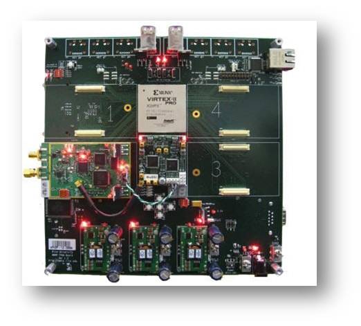
Details on the WARP MIMO Kit v2 can be found http://mangocomm.com/products/kits/warp-mimo-kit-v2. Each WARP SDR in w-iLab.2 consists of a WARP FPGA Board v2.2, a WARP Clock Board v1.1 and two WARP Radio Boards v1.4.
There are 3 WARP SDRs installed in w-iLab.2. They are connected over JTAG USB to zotacF3, zotacG3 and zotacH3 (verify on the inventory). You need to reserve the correct zotac node to configure the FPGA and firmware on the WARP SDR.
Apart from the JTAG connection, the each WARP also has an Ethernet interface that is patched to the experiment switch and therefore can be connected to an experiment interface on one of the servers, this is different than USRP N210.
For setting up an experiment in jFed, you do need to draw links between the WARP and a given server, and specify the IP address on the server’s interface. The IP address of WARP depends on the firmware configuration, for using WARP as an sensing engine, the IP address is 10.0.0.1/24. For Emulab experiment, the WARP devices have to be reserved on the reservation page before they can be used in an experiment, and similar to jFed the link between server and WARP SDR needs to be defined (configure the server side with e.g. ifconfig eth4 10.0.0.2/24).
Dedicated spectrum sensing devices
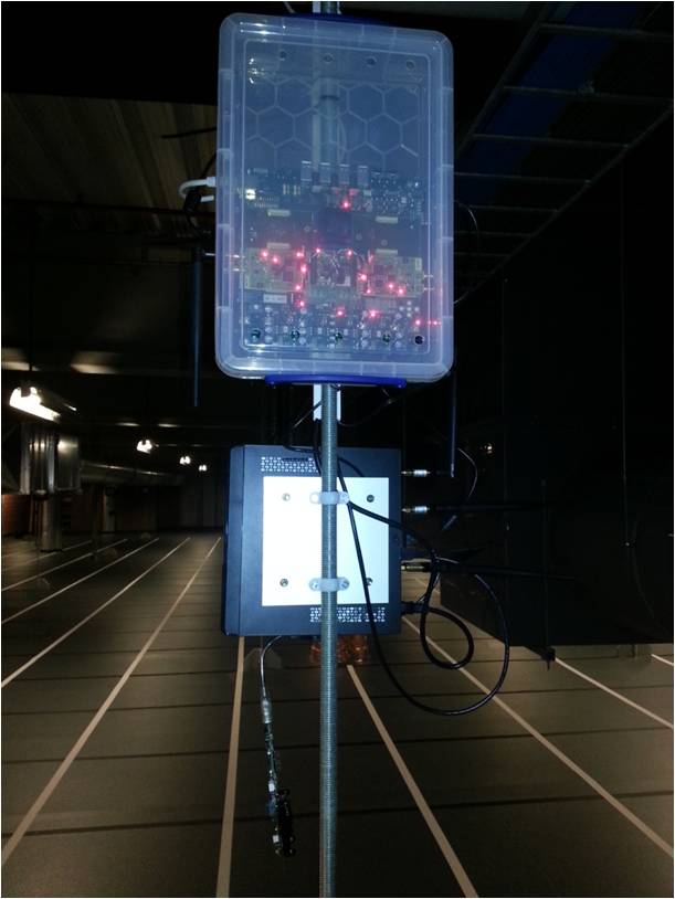
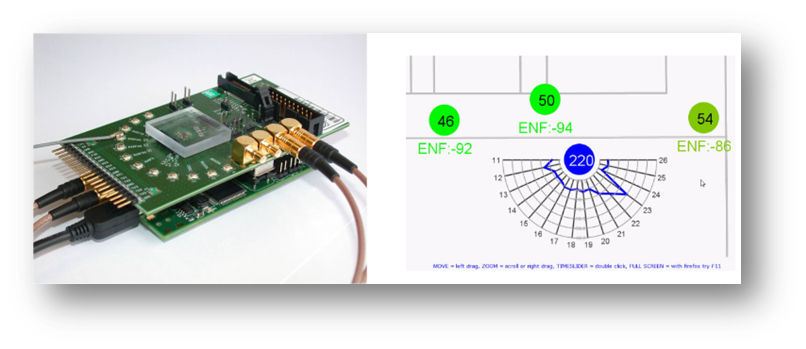
imec SE
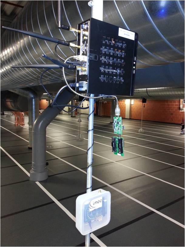
The imec sensing engine is a prototype implementation of a sensing engine for mobile communication devices. The prototype consists of two main blocks: an analog RF front-end including analog to digital conversion and a DIgital Front-end For Sensing (DIFFS). For permanent deployment in the w-iLab.2 testbed a WARP board is selected as analog RF front-end, covering the 2.4 and 5 GHz ISM bands. An in house developed flexibele SCAlable raDIO (SCALDIO) is also tested in a lab environment, covering an RF input range from 0.1 up to 6 GHz and a channel bandwidth up to 40 MHz. The digital front-end is an ASIP specifically designed for sensing operations, signal conditioning and synchronization. The chip contains a flexible filter block, including re-sampling and a SIMD core, extended with multiple accelerator cores. Multiple sensing algorithms are implemented on the system, ranging from straight-forward energy detection schemes, over more complex feature detection (for e.g. DVB-T) to multiband energy detection after FFT leakage removal for OFDMA LTE signals.
The imec sensing engines in w-iLab.2 are connected as USB devices to some of the wireless nodes. Four nodes have an imec SE attached with WARP_FE (zotacC2, zotacF4, zotacJ2 and dssJ5), two nodes have an imec SE attached with SCALDIO_FE (zotacJ3 and zotacJ4).
The imec SE devices cannot be reserved or swapped in through the webinterface. If you want to use these devices, it is sufficient to reserve the wireless nodes where the SE’s are connected to.
Wi-Spy
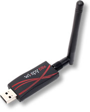
The Wi-Spy is a commercially available USB dongle that allows you to do spectrum scanning on 2.4 and 5GHz. Check out the Wi-Spy home page for more details.
There are currently 3 Wi-Spy devices deployed in w-iLab.2 as USB extensions to some of the wireless nodes: zotacC3, zotacF4 and dssJ5. Please verify on the inventory that these locations are still accurate. The Wi-Spy devices cannot be reserved or swapped in through the webinterface. If you want to use these devices, it is sufficient to reserve the wireless nodes where the Wi-Spy’s are connected to.
Mobility extension
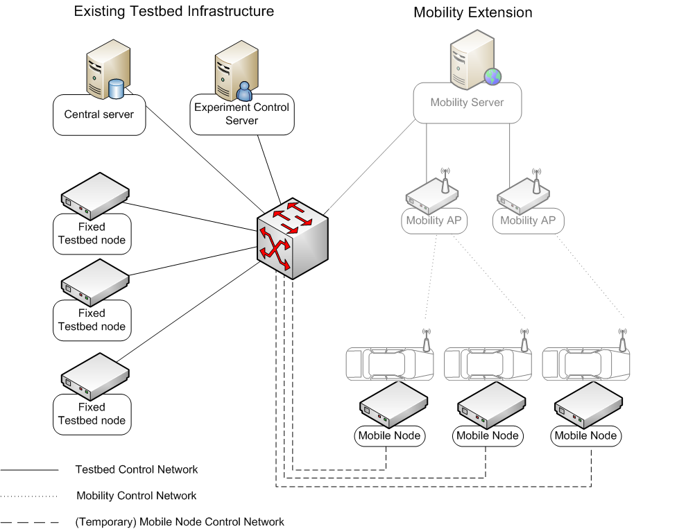
Some nodes in w-iLab.2 are of type MOBILE. These nodes can be used in the same way as the other testbed nodes, while having the extra capability of moving across the testbed floor during the experiment.
The figure below shows the different components of the real life mobility toolkit. The left side of the figure depicts the simplified architecture of an existing testbed, whereas the right side of the figure shows the blocks which are needed to enable mobility in the testbed. The goal of the mobility extension is to enable the use of mobile nodes in the testbed. Therefore, the components that are needed to control the mobility extension are shown as transparent, and are also transparent for the experimenter.
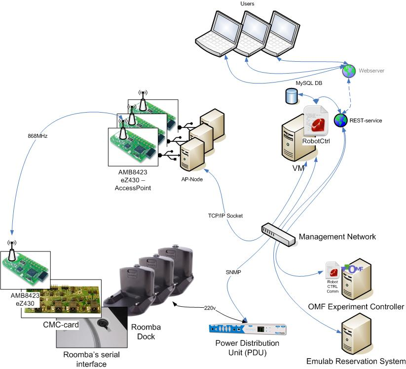
The figure below shows the architecture of the mobility toolkit specific for the iMinds w-iLab.t deployment, with focus on the management side:
- The users connect to the framework via a REST-service (made userfriendly through a webgui: RobotDashboard).
- The REST-service (RobotControl) is a central entity through which every command is validated and that distributes the commands among the RobotAP’s, so the LPE (Localisation and Positioning Engine) on the robot knows what to do.
- RobotControl can also be approched via OMF-scripts and talks to Emulab to enable authentication.
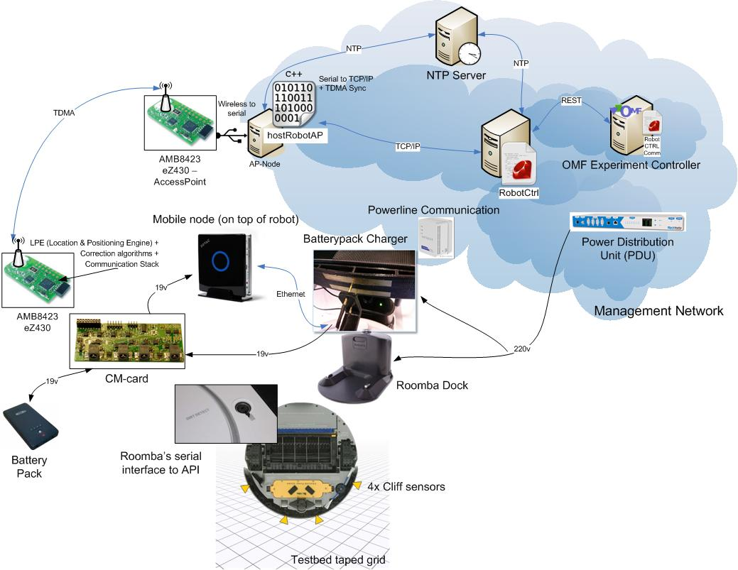
The next scheme details the framework on the robot end:
- When the robot is docked, an ethernet connection to the mobile node is provided.
- When the robot is driving, it has no connection to the management network by default. Docking re-enables the ethernet interface automatically.
Qosmotec platform
The qosmotec boxes are useful for doing wireless experiments in a controlled environment (i.e.: no outside interference, controllable attenuation, controllable topology).
Official documentation
Extra documentation
LTE equipment
Overview
The W-iLab.t testbed offers various ways of LTE experimentation. Currently, the testbed provides two (2) different fully operational LTE networks. The one has been deployed in the IBCN’s premices in Zwijnaarde (W.iLab.t LTE testbed deployment) and the other has been deployed in fully shielded (RF-isolated) boxes (Qosmotec LTE deployment).
SiRRAN EPC
Important notes:
- Only one instance of the EPC server can run each time, as only one licence can be enabled at any given time.
- To enable the license, the eth1 interface of the server hosting the EPC image must be up and configured. In case that more than one experiment interfaces are available (e.g. the SERVER5P servers offer 5 experiment interfaces) the one that will be used is randomly selected.
- If the eth1 interface is not the one which is randomly selected, then it should be brought up. Use the ifconfig command to verify the selected interface. Assuming that the eth3 is randomly selected, then the following commands should be issued:
sudo su
ifconfig eth3 192.168.1.X // X must be an unused address different that 1. The eth3 must remain up due to compatibility issues with JFED
ifconfig eth1 192.168.1.1 up
sudo /etc/init.d/ltenet restart
- Alternatively, a “temporary server” can be used to create links with all the available experiment interfaces of the EPC node.
- In JFED, multiple links between the EPC server and the temporary server can be drawn. The rspec example bellow creates 5 links between the 5 available interfaces of server4 (to be used as EPC server) and server5 (to be used as temporary server). As can be seen the eth1 interface of server4 has been set to the desirable IPv4 (192.168.1.1) for the EPC. Different IPs can be assigned to all the other interfaces of server4 and the temporary server.
<?xml version='1.0'?>
<rspec xmlns="http://www.geni.net/resources/rspec/3" type="request" generated_by="jFed RSpec Editor" generated="2016-06-27T10:46:14.193+02:00" xmlns:emulab="http://www.protogeni.net/resources/rspec/ext/emulab/1" xmlns:jfedBonfire="http://jfed.iminds.be/rspec/ext/jfed-bonfire/1" xmlns:delay="http://www.protogeni.net/resources/rspec/ext/delay/1" xmlns:jfed-command="http://jfed.iminds.be/rspec/ext/jfed-command/1" xmlns:client="http://www.protogeni.net/resources/rspec/ext/client/1" xmlns:jfed-ssh-keys="http://jfed.iminds.be/rspec/ext/jfed-ssh-keys/1" xmlns:jfed="http://jfed.iminds.be/rspec/ext/jfed/1" xmlns:sharedvlan="http://www.protogeni.net/resources/rspec/ext/shared-vlan/1" xmlns:xsi="http://www.w3.org/2001/XMLSchema-instance" xsi:schemaLocation="http://www.geni.net/resources/rspec/3 http://www.geni.net/resources/rspec/3/request.xsd ">
  <node client_id="Server4" exclusive="true" component_manager_id="urn:publicid:IDN+wilab2.ilabt.imec.be+authority+cm" component_id="urn:publicid:IDN+wilab2.ilabt.imec.be+node+server4">
    <sliver_type name="raw-pc"/>
    <location xmlns="http://jfed.iminds.be/rspec/ext/jfed/1" x="117.0" y="195.5"/>
    <interface client_id="Server4:if0">
      <ip address="192.168.1.1" netmask="255.255.255.0" type="ipv4"/>
    </interface>
    <interface client_id="Server4:if1">
      <ip address="192.168.2.2" netmask="255.255.255.0" type="ipv4"/>
    </interface>
    <interface client_id="Server4:if2">
      <ip address="192.168.3.3" netmask="255.255.255.0" type="ipv4"/>
    </interface>
    <interface client_id="Server4:if3">
      <ip address="192.168.4.4" netmask="255.255.255.0" type="ipv4"/>
    </interface>
    <interface client_id="Server4:if4">
      <ip address="192.168.5.5" netmask="255.255.255.0" type="ipv4"/>
    </interface>
  </node>
  <node client_id="Server5" exclusive="true" component_manager_id="urn:publicid:IDN+wilab2.ilabt.imec.be+authority+cm" component_id="urn:publicid:IDN+wilab2.ilabt.imec.be+node+server5">
    <sliver_type name="raw-pc"/>
    <location xmlns="http://jfed.iminds.be/rspec/ext/jfed/1" x="379.5" y="191.5"/>
    <interface client_id="Server5:if0">
      <ip address="192.168.14.2" netmask="255.255.255.0" type="ipv4"/>
    </interface>
    <interface client_id="Server5:if1">
      <ip address="192.168.15.2" netmask="255.255.255.0" type="ipv4"/>
    </interface>
    <interface client_id="Server5:if2">
      <ip address="192.168.16.2" netmask="255.255.255.0" type="ipv4"/>
    </interface>
    <interface client_id="Server5:if3">
      <ip address="192.168.17.2" netmask="255.255.255.0" type="ipv4"/>
    </interface>
    <interface client_id="Server5:if4">
      <ip address="192.168.18.2" netmask="255.255.255.0" type="ipv4"/>
    </interface>
  </node>
  <link client_id="link0">
    <component_manager name="urn:publicid:IDN+wilab2.ilabt.imec.be+authority+cm"/>
    <interface_ref client_id="Server4:if0"/>
    <interface_ref client_id="Server5:if0"/>
    <link_type name="lan"/>
  </link>
  <link client_id="link1">
    <component_manager name="urn:publicid:IDN+wilab2.ilabt.imec.be+authority+cm"/>
    <interface_ref client_id="Server4:if1"/>
    <interface_ref client_id="Server5:if1"/>
    <link_type name="lan"/>
  </link>
  <link client_id="link2">
    <component_manager name="urn:publicid:IDN+wilab2.ilabt.imec.be+authority+cm"/>
    <interface_ref client_id="Server4:if2"/>
    <interface_ref client_id="Server5:if2"/>
    <link_type name="lan"/>
  </link>
  <link client_id="link3">
    <component_manager name="urn:publicid:IDN+wilab2.ilabt.imec.be+authority+cm"/>
    <interface_ref client_id="Server4:if3"/>
    <interface_ref client_id="Server5:if3"/>
    <link_type name="lan"/>
  </link>
  <link client_id="link4">
    <component_manager name="urn:publicid:IDN+wilab2.ilabt.imec.be+authority+cm"/>
    <interface_ref client_id="Server4:if4"/>
    <interface_ref client_id="Server5:if4"/>
    <link_type name="lan"/>
  </link>
</rspec>
Deprecated usage
In Emulab, the following model NS file that can be used when a SERVER5P is selected to host the EPC image. In this example, server4 hosts the SiRRAN EPC, while server5 is used as a “temporary server” to create links with all the available experiment interfaces of server4.
# Generated by NetlabClient
set ns [new Simulator]
source tb_compat.tcl

# Nodes

# Femtocell 1
set lte1 [$ns node]
$lte1 add-desire LTE-FEMTOCELL 1.0

tb-fix-node $lte1 ltefemtocell1

# Femtocell 2
set lte2 [$ns node]
$lte2 add-desire LTE-FEMTOCELL 1.0
tb-fix-node $lte2 ltefemtocell2

# Node 4 - SiRRAN EPC
set serv4 [$ns node]
$serv4 add-desire SERVER1P 1.0
tb-fix-node $serv4 server4
tb-set-node-os $serv4 #urn_of_the_EPC_image_goes_here

# Temporary server to set link with the eth1 interface of server 6
 set tempserv [$ns node]
 $tempserv add-desire SERVER5P 1.0
 tb-fix-node $tempserv server5

# Lans
set lan0 [$ns make-lan "$serv4 $tempserv" 1000000.0kb 0.0ms]
set lan1 [$ns make-lan "$serv4 $tempserv" 1000000.0kb 0.0ms]
set lan2 [$ns make-lan "$serv4 $tempserv" 1000000.0kb 0.0ms]
set lan3 [$ns make-lan "$serv4 $tempserv" 1000000.0kb 0.0ms]
set lan4 [$ns make-lan "$serv4 $tempserv" 1000000.0kb 0.0ms]

set lan0 [$ns make-lan "$lte1 $lte2 $serv4" 1000000.0kb 0.0ms]

tb-set-ip-lan $serv6 $lan0 192.168.1.1
tb-set-ip-lan $serv6 $lan1 192.168.2.2
tb-set-ip-lan $serv6 $lan2 192.168.3.3
tb-set-ip-lan $serv6 $lan3 192.168.4.4
tb-set-ip-lan $serv6 $lan4 192.168.5.5

$ns rtproto Static
$ns run

# NetlabClient generated file ends here.
# Finished at: 3/18/14 4:08 PM
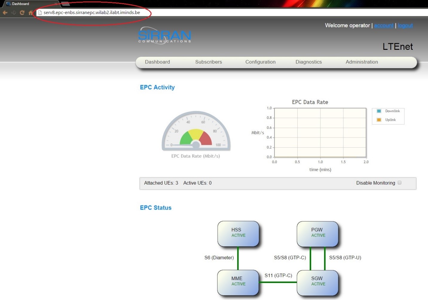
- Username: operator
- Password: 0Perato$
The next figure depitcs the SiRRAN EPC web GUI.
ip.access femtocell
IBCN provides a commercial LTE Access Network, which comprises of four (4) femtocells (LTE 245F) provided by ip.access. These femtocells can be configured in two LTE spectrum bands (7 and 13). Test frequencies in the licensed LTE band 7, are assigned by the Belgian Institute for Postal services and Telecommunications (BIPT), to be used for experimental purposes. Hence, the femtocells are configured to operate in that band.
1st femtocell
- eth0 IP: 192.168.2.10
- eth1 IP: 192.168.1.10
- eth0 Bcast: 192.168.2.255
- eth1 Bcast: 192.168.1.255
- Mask: 255.255.255.0
- Cell Identity: 2055
2nd femtocell
- eth0 IP: 192.168.2.11
- eth1 IP: 192.168.1.11
- eth0 Bcast: 192.168.2.255
- eth1 Bcast: 192.168.1.255
- Mask: 255.255.255.0
- Cell Identity: 2056
3th femtocell
- eth0 IP: 192.168.2.12
- eth1 IP: 192.168.1.12
- eth0 Bcast: 192.168.2.255
- eth1 Bcast: 192.168.1.255
- Mask: 255.255.255.0
- Cell Identity: 2057
4th femtocell
- eth0 IP: 192.168.2.13
- eth1 IP: 192.168.1.13
- eth0 Bcast: 192.168.2.255
- eth1 Bcast: 192.168.1.255
- Mask: 255.255.255.0
- Cell Identity: 2058
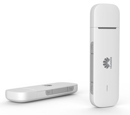
Huawei E398u1 LTE USB Dongle UE
W-iLab.t has been equipped with 25 commercial LTE dongles by Huawei to be used as LTE UE (User Equipment). Some of these dongles are mounted on each mobile Zotac node, which is attached on a Roomba robot, in order to provide the required controlled mobility experimentation. In addition, some extra dongles are mounted on static Zotac nodes. All the UEs are 100% unlocked for worldwide use and can be fully configured via AT commands (see section 2.3.2). The dongles are compatible with the LTE FDD band 7 and are interoperable with the deployed LTE network. The obtained dongles are the Huawei E398u-1 4G LTE USB Modems. Huawei E398u-1 modem is a fast speed (Download up to 100 Mbps - Upload up to 50 Mbps) LTE card. It is a triple-mode LTE modem that enables seamlessly switching between 2G GSM/GPRS/EDGE (850/900/1800/1900 MHz), 3G UMTS (900/2100 MHz) and 4G LTE FDD (900/1800/2100/2600 MHz).

The following table summarizes the specifications of the LTE dongles.
| LTE Dongle | Available Dongles | Technical Specifications |
|---|---|---|
| Huawei E398u-1 | 25 | Dongle |
| 4G Frequency: LTE FDD 900 / 1800 / 2100 / 2600 MHz | ||
| 3G Frequency: UMTS 900 / 2100 Mhz | ||
| 2G Frequency: GSM / GPRS / EDGE - 850 / 900 / 1800 / 1900 Mhz | ||
| LTE download Speed up to 100 Mbit/s | ||
| LTE upload Speed up to 50 Mbit/s | ||
| LTE 2x2 MIMO | ||
| Antenna: Integral antenna. 2X External antenna interface | ||
| Memory: Micro SD card slot up to 32GB | ||
| Display: LED Indicator | ||
| Size: 90 x 25 x 15mm | ||
| Weight: 40g |
The table below presents the USIM card’s IMSI number and the corresponding UE’s IMEI for each node equipped with an LTE dongle.
| ID | IMSI | Node | UE type | IMEI |
|---|---|---|---|---|
| 1 | 223451234567880 | Node 38 (Zotac G4) | Dongle Huawei E398u1 | N/A |
| 2 | 223451234567881 | Robot 2 | Dongle Huawei E398u1 | N/A |
| 3 | 223451234567882 | Node 42 (Zotac K4) | Dongle Huawei E398u1 | N/A |
| 4 | 223451234567883 | Robot 4 | Dongle Huawei E398u1 | N/A |
| 5 | 223451234567884 | Node 33 (Zotac B4) | Dongle Huawei E398u1 | N/A |
| 6 | 223451234567885 | Robot 6 | Dongle Huawei E398u1 | N/A |
| 7 | 223451234567886 | Node 57 (Zotac H6) | Dongle Huawei E398u1 | N/A |
| 8 | 223451234567887 | Robot 8 | Dongle Huawei E398u1 | N/A |
| 9 | 223451234567888 | Node 5 (Zotac F1) | Dongle Huawei E398u1 | N/A |
| 10 | 223451234567889 | Robot 10 | Dongle Huawei E398u1 | N/A |
| 11 | 223451234567890 | Node 27 (Zotac G3) | Dongle Huawei E398u1 | N/A |
| 12 | 223451234567891 | Robot 12 | Dongle Huawei E398u1 | N/A |
| 13 | 223451234567892 | Node 55 (Zotac F6) | Dongle Huawei E398u1 | N/A |
| 14 | 223451234567893 | Robot 14 | Dongle Huawei E398u1 | N/A |
| 15 | 223451234567894 | Node 29 (Zotac I3) | Dongle Huawei E398u1 | N/A |
| 16 | 223451234567895 | Node 7 (Zotac H1) | Dongle Huawei E398u1 | N/A |
| 17 | 223451234567896 | Node 25 (Zotac E3) | Dongle Huawei E398u1 | N/A |
| 18 | 223451234567897 | Node 2 (Zotac C1) | Dongle Huawei E398u1 | N/A |
| 19 | 223451234567898 | Node 54 (Zotac D6) | Dongle Huawei E398u1 | N/A |
| 20 | 223451234567899 | Node 34 (Zotac C4) | Dongle Huawei E398u1 | N/A |
| 21 | 223451234567900 | Node 19 (Zotac J2) | Dongle Huawei E398u1 | N/A |
| 22 | 223451234567901 | Node 22 (Zotac B3) | Dongle Huawei E398u1 | N/A |
| 23 | 223451234567902 | Node 30 (Zotac J3) | Dongle Huawei E398u1 | N/A |
| 24 | 223451234567903 | Qosmotec Shielded Box 2 (Zotac SB3) | Dongle Huawei E398u1 | N/A |
| 25 | 223451234567904 | Qosmotec Shielded Box 4 (Zotac SB4) | Dongle Huawei E398u1 | N/A |
Android Nexus 6P Smartphone
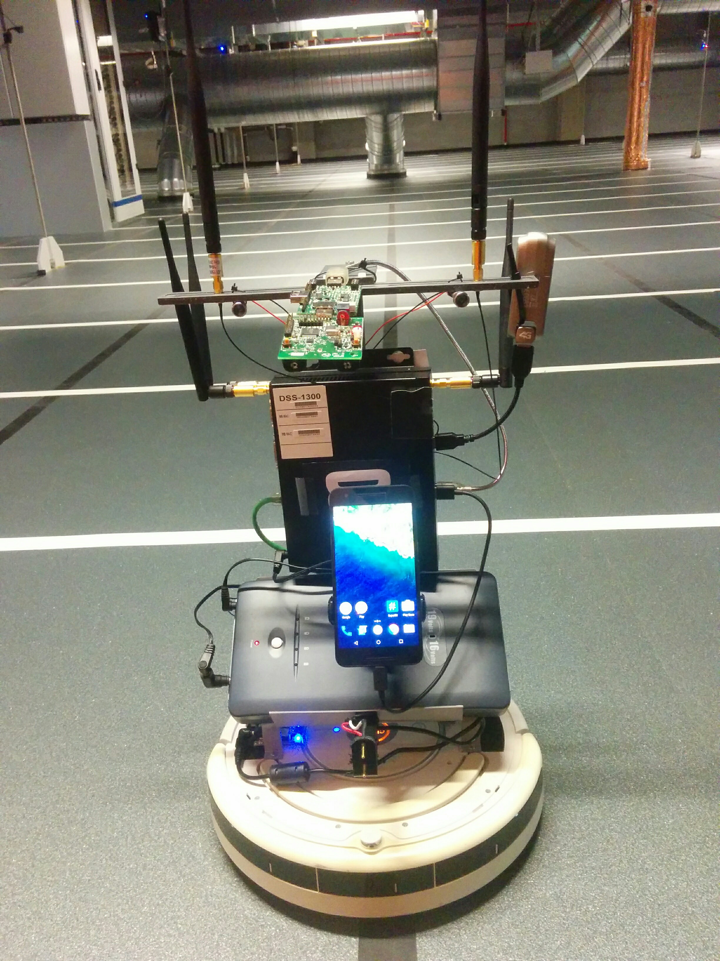
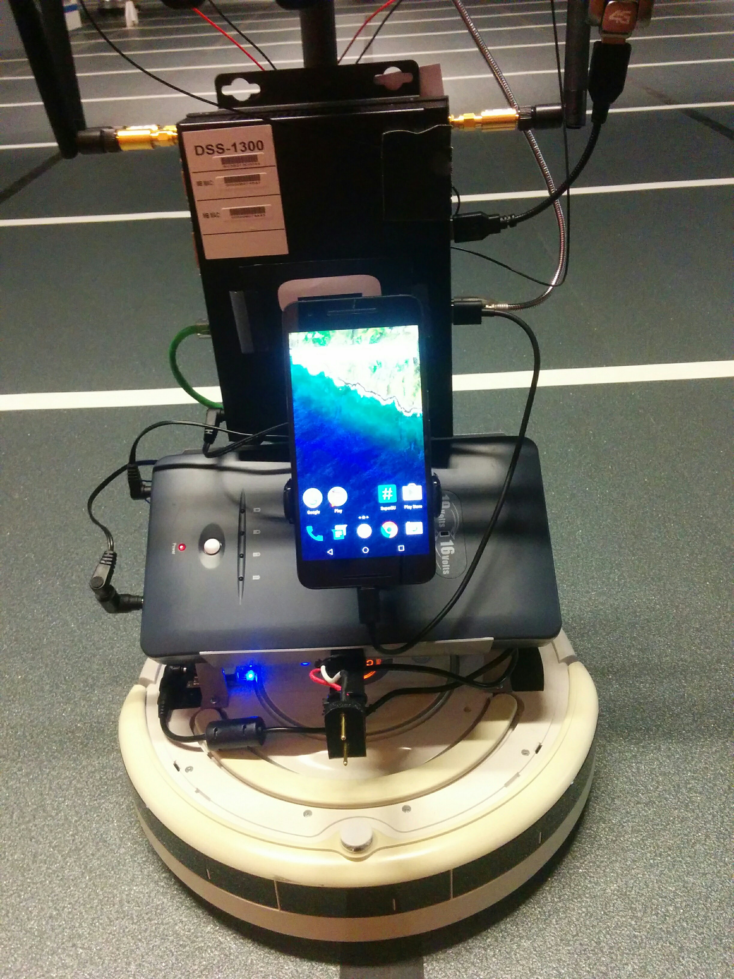
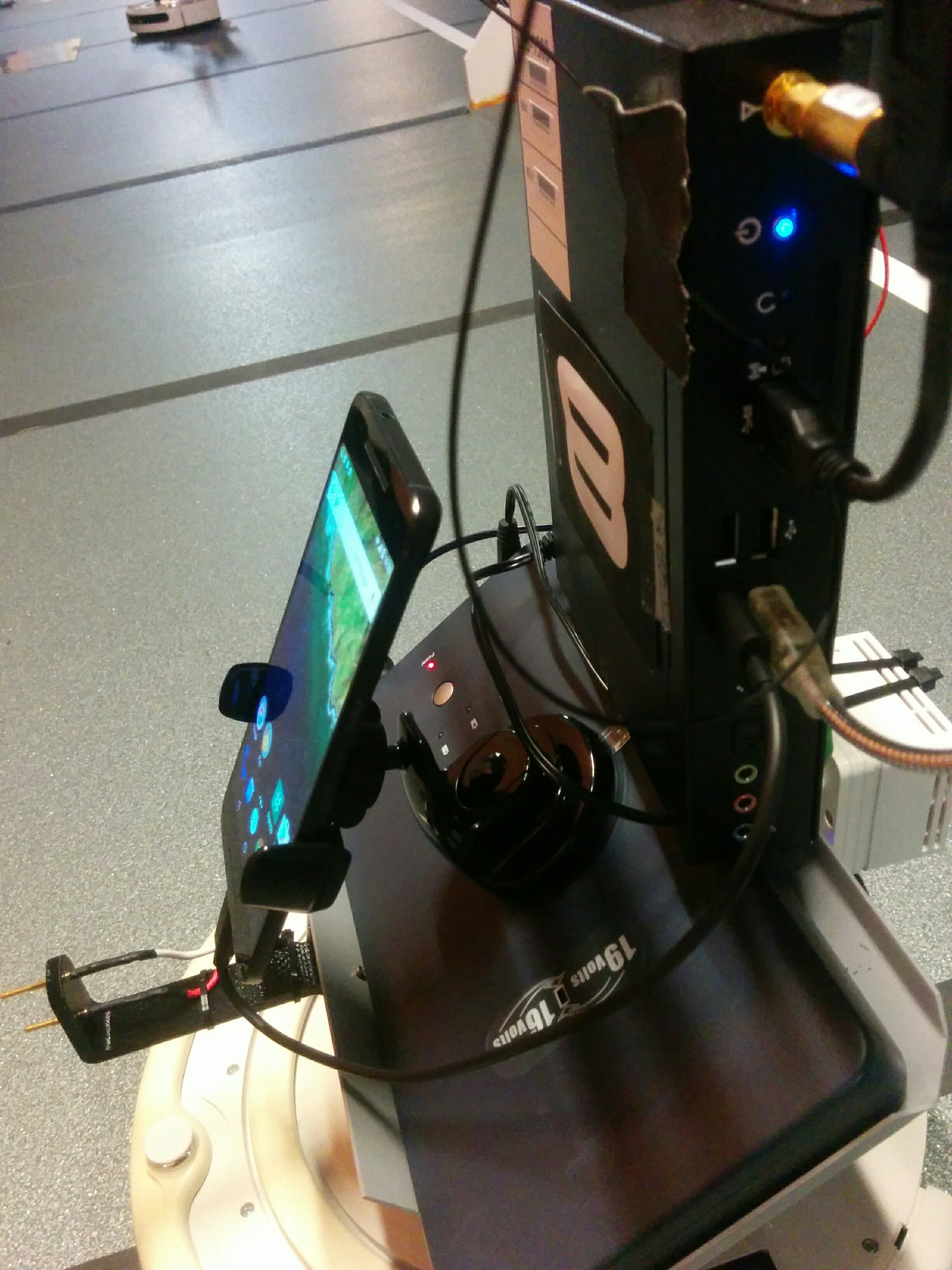
W-iLab.t has been equipped with 15 Android Nexus 6P smartphones to be used as LTE UE (User Equipment). These smartphones are mounted on each mobile Zotac node, which is attached on a Roomba robot, in order to provide the required controlled mobility experimentation. The smartphones are compatible with the LTE FDD band 7 and are interoperable with the deployed LTE network.

The following photos show the way that the smartphone are mounted on the mobile nodes.
The following table summarizes the specifications of the Android Nexus 6P smartphones.
| Smartphone | Available devices | Technical Specifications |
|---|---|---|
| Android Nexus 6P | 15 | Smartphone |
| LTE / HSPA / CDMA / GSM | ||
| Android OS, v6.0 (Marshmallow) | ||
| Qualcomm MSM8994 Snapdragon 810 | ||
| 3GB RAM | ||
| Memory: 64GB | ||
| Camera: Primary 12.3 MP - Secondary 8 MP | ||
| Wi-Fi 802.11 a/b/g/n/ac, dual-band, Wi-Fi Direct, DLNA, hotspot | ||
| Bluetooth v4.2, A2DP, LE | ||
| Display: AMOLED capacitive touchscreen, 16M colors, 5.7 inches | ||
| Resolution: 1440 x 2560 pixels | ||
| Size: 159.3 x 77.8 x 7.3 mm | ||
| Weight: 178g |
The table below presents the USIM card’s IMSI number and the corresponding UE’s IMEI for each node equipped with an Android Nexus 6P Smartphone.
| ID | IMSI | Node | UE type | IMEI |
|---|---|---|---|---|
| 26 | 223451234567905 | Robot 1 | Android Nexus 6P | 867981021914430 |
| 27 | 223451234567906 | Robot 2 | Android Nexus 6P | 867981021915148 |
| 28 | 223451234567907 | Robot 3 | Android Nexus 6P | 867981021910966 |
| 29 | 223451234567908 | Robot 4 | Android Nexus 6P | 867981021917169 |
| 30 | 223451234567909 | Robot 5 | Android Nexus 6P | 867981021915015 |
| 31 | 223451234567910 | Robot 6 | Android Nexus 6P | 867981021916203 |
| 32 | 223451234567911 | Robot 7 | Android Nexus 6P | 867981021912038 |
| 33 | 223451234567912 | Robot 8 | Android Nexus 6P | 867981021912350 |
| 34 | 223451234567913 | Robot 9 | Android Nexus 6P | 867981021913820 |
| 35 | 223451234567914 | Robot 10 | Android Nexus 6P | 867981021917698 |
| 36 | 223451234567915 | Robot 11 | Android Nexus 6P | 867981021917748 |
| 37 | 223451234567916 | Robot 12 | Android Nexus 6P | 867981021914380 |
| 38 | 223451234567917 | Robot 13 | Android Nexus 6P | 867981021915866 |
| 39 | 223451234567918 | Robot 14 | Android Nexus 6P | 867981021917367 |
| 40 | 223451234567919 | Robot 15 | Android Nexus 6P | 867981021917649 |
Huawei E3372h-153 LTE USB Dongle UE
W-iLab.t has been equipped with 10 Huawei E3372h Category 4 USB dongles to be used as LTE UE (User Equipment).
The dongles are configured in HiLink mode. This means that the dongle functions as router performing NAT. For this reason, HiLink mode cannot be used for remote access applications (e.g. Remote Desktop, VNC, web servers, etc.) where “inbound” connections are initiated by computers on the Internet. To use HiLink mode, your application must require only “outbound” initiated connections (e.g. web browsing, email, etc.), or you must implement a VPN connection to another device which is initiated by the router which has the HiLink mode modem installed.
For LTE experimentation using the Huawei E3372h-153 dongles please refer to the tutorial in the related section.
The following table summarizes the specifications of the LTE dongles.
| LTE Dongle | Available Dongles | Technical Specifications |
|---|---|---|
| Huawei E3372h-153 | 10 | Dongle |
| 4G Frequency: FDD DD800/900/1800/2100/2600 | ||
| 3G Frequency: UMTS 900 / 2100 Mhz | ||
| 2G Frequency: GSM / GPRS / EDGE - 850 / 900 / 1800 / 1900 Mhz | ||
| LTE download Speed up to 150 Mbit/s | ||
| LTE upload Speed up to 50 Mbit/s | ||
| LTE 2x2 MIMO | ||
| Antenna: Integral antenna. 2X External antenna interface | ||
| Memory: Micro SD card slot | ||
| Display: LED Indicator | ||
| Size: 88 x 28 x 11.5mm | ||
| Weight: <35g |
The table below presents the USIM card’s IMSI number and the corresponding UE’s IMEI for each node equipped with an LTE dongle.
| ID | IMSI | Node | UE type | IMEI |
|---|---|---|---|---|
| 41 | 223451234567920 | Huawei E3372h-153 | 861821034190675 | |
| 42 | 223451234567921 | Huawei E3372h-153 | 861821034190824 | |
| 43 | 223451234567922 | Huawei E3372h-153 | 861821034190832 | |
| 44 | 223451234567923 | Huawei E3372h-153 | 861821034190857 | |
| 45 | 223451234567924 | Huawei E3372h-153 | 861821034190964 | |
| 46 | 223451234567925 | Huawei E3372h-153 | 861821034190261 | |
| 47 | 223451234567926 | Huawei E3372h-153 | 861821034190865 | |
| 48 | 223451234567927 | Huawei E3372h-153 | 861821034190717 | |
| 49 | 223451234567928 | Huawei E3372h-153 | 861821034190287 | |
| 50 | 223451234567929 | Huawei E3372h-153 | 861821034190022 |
LTE SIM cards
IBCN has purchased 50 USIM cards from Smartjac. The SIM cards are LTE compatible and they are preconfigured by Smartjac according to the IBCN desirable parameters. The cards are shipped as Mini-SIM or Nano-SIM size (2FF) to be compatible with the available LTE UEs.
The following table summarizes the specifications of the USIM cards of the W-iLab.t testbed.
| SIM Card model | Quantity | Technical Specifications |
|---|---|---|
| Smartjac 3G cards with 4G support | 40 | USIM cards |
| Authentication algorithm: Milenage | ||
| K code: 0x00112233445566778899AABBCCDDEEFF | ||
| OP code : 0x01020304050607080910111213141516 | ||
| OPc: 0x0ED47545168EAFE2C39C075829A7B61F | ||
| IMSI ranges: 223451234567880 – 223451234567904 | ||
| SPN: iMinds Network |
The table below presents the USIM card’s IMSI number and the corresponding UE’s IMEI for each node equipped with an LTE dongle or an Android Smartphone.
| ID | IMSI | Node | UE type | IMEI |
|---|---|---|---|---|
| 1 | 223451234567880 | Node 38 (Zotac G4) | Dongle Huawei E398u1 | N/A |
| 2 | 223451234567881 | Mobile 2 | Dongle Huawei E398u1 | N/A |
| 3 | 223451234567882 | Node 42 (Zotac K4) | Dongle Huawei E398u1 | N/A |
| 4 | 223451234567883 | Mobile 4 | Dongle Huawei E398u1 | N/A |
| 5 | 223451234567884 | Node 33 (Zotac B4) | Dongle Huawei E398u1 | N/A |
| 6 | 223451234567885 | Mobile 6 | Dongle Huawei E398u1 | N/A |
| 7 | 223451234567886 | Node 57 (Zotac H6) | Dongle Huawei E398u1 | N/A |
| 8 | 223451234567887 | Mobile 8 | Dongle Huawei E398u1 | N/A |
| 9 | 223451234567888 | Node 5 (Zotac F1) | Dongle Huawei E398u1 | N/A |
| 10 | 223451234567889 | Mobile 10 | Dongle Huawei E398u1 | N/A |
| 11 | 223451234567890 | Node 27 (Zotac G3) | Dongle Huawei E398u1 | N/A |
| 12 | 223451234567891 | Mobile 12 | Dongle Huawei E398u1 | N/A |
| 13 | 223451234567892 | Node 55 (Zotac F6) | Dongle Huawei E398u1 | N/A |
| 14 | 223451234567893 | Mobile 14 | Dongle Huawei E398u1 | N/A |
| 15 | 223451234567894 | Node 29 (Zotac I3) | Dongle Huawei E398u1 | N/A |
| 16 | 223451234567895 | Node 7 (Zotac H1) | Dongle Huawei E398u1 | N/A |
| 17 | 223451234567896 | Node 25 (Zotac E3) | Dongle Huawei E398u1 | N/A |
| 18 | 223451234567897 | Node 2 (Zotac C1) | Dongle Huawei E398u1 | N/A |
| 19 | 223451234567898 | Node 54 (Zotac D6) | Dongle Huawei E398u1 | N/A |
| 20 | 223451234567899 | Node 34 (Zotac C4) | Dongle Huawei E398u1 | N/A |
| 21 | 223451234567900 | Node 19 (Zotac J2) | Dongle Huawei E398u1 | N/A |
| 22 | 223451234567901 | Node 22 (Zotac B3) | Dongle Huawei E398u1 | N/A |
| 23 | 223451234567902 | Node 30 (Zotac J3) | Dongle Huawei E398u1 | N/A |
| 24 | 223451234567903 | Qosmotec Shielded Box 2 (Zotac SB3) | Dongle Huawei E398u1 | N/A |
| 25 | 223451234567904 | Qosmotec Shielded Box 4 (Zotac SB4) | Dongle Huawei E398u1 | N/A |
| 26 | 223451234567905 | Mobile 1 | Android Nexus 6P | 867981021914430 |
| 27 | 223451234567906 | Mobile 2 | Android Nexus 6P | 867981021915148 |
| 28 | 223451234567907 | Mobile 3 | Android Nexus 6P | 867981021910966 |
| 29 | 223451234567908 | Mobile 4 | Android Nexus 6P | 867981021917169 |
| 30 | 223451234567909 | Mobile 5 | Android Nexus 6P | 867981021915015 |
| 31 | 223451234567910 | Mobile 6 | Android Nexus 6P | 867981021916203 |
| 32 | 223451234567911 | Mobile 7 | Android Nexus 6P | 867981021912038 |
| 33 | 223451234567912 | Mobile 8 | Android Nexus 6P | 867981021912350 |
| 34 | 223451234567913 | Mobile 9 | Android Nexus 6P | 867981021913820 |
| 35 | 223451234567914 | Mobile 10 | Android Nexus 6P | 867981021917698 |
| 36 | 223451234567915 | Mobile 11 | Android Nexus 6P | 867981021917748 |
| 37 | 223451234567916 | Mobile 12 | Android Nexus 6P | 867981021914380 |
| 38 | 223451234567917 | Mobile 13 | Android Nexus 6P | 867981021915866 |
| 39 | 223451234567918 | Mobile 14 | Android Nexus 6P | 867981021917367 |
| 40 | 223451234567919 | Mobile 15 | Android Nexus 6P | 867981021917649 |
| 41 | 223451234567920 | Huawei E3372h-153 | 861821034190675 | |
| 42 | 223451234567921 | Huawei E3372h-153 | 861821034190824 | |
| 43 | 223451234567922 | Huawei E3372h-153 | 861821034190832 | |
| 44 | 223451234567923 | Huawei E3372h-153 | 861821034190857 | |
| 45 | 223451234567924 | Huawei E3372h-153 | 861821034190964 | |
| 46 | 223451234567925 | Huawei E3372h-153 | 861821034190261 | |
| 47 | 223451234567926 | Huawei E3372h-153 | 861821034190865 | |
| 48 | 223451234567927 | Huawei E3372h-153 | 861821034190717 | |
| 49 | 223451234567928 | Huawei E3372h-153 | 861821034190287 | |
| 50 | 223451234567929 | Huawei E3372h-153 | 861821034190022 |
LTErf OMF service
LTErf is an OMF Aggregate Manager service that enables controlling of the ip.access LTE 245F femtocells and of SiRRAN’s EPC Network.
OMF stands for cOntrol and Management Framework and is a generic tool that allows an experimenter to configure the resources of a testbed, as well as to manage and execute his/her experiment using a domain-specific language, named OEDL. According to the OMF’s architecture, the user provides to the framework his/her Experiment’s Description (ED) written in OEDL. Then the Experiment Controller (EC) interprets the ED, and sends requests to the Aggregate Manager (AM) of the testbed to ask for the initialization and configuration of the experimenter’s required resources. The multiple services of the AM initialize and configure these resources. When the resources are ready, the EC sends commands to the Resource Controllers (RCs), which run on each of these resources. Then, the RCs interpret these commands and execute the actions.
Currently, LTErf can be used to get and set values from the APs as well as to get values from SiRRAN’s EPC. The values that can be changed/reported are the ones that are visible to the testbed Operator and can be used for setting up an experiment.
The AP IDs are given based on the sequence of the IP addresses given in the configuration file. According to the IBCN configuration file the correspondence between the femtocell’s IDs, the femtocells’ IP and the femtocell’s location is the following:
| Femtocell ID | Femtocell IP | Femtocell location |
|---|---|---|
| Node 1 | 192.168.1.10 | W-iLab.t testbed |
| Node 2 | 192.168.1.11 | W-iLab.t testbed |
| Node 3 | 192.168.1.12 | Qosmotec |
| Node 4 | 192.168.1.13 | Qosmotec |
Useful LTErf commands
GET the MCS Downlink and Uplink profiles from node 1:
- wget -qO- “http://localhost:5054/lterf/bs/get?MCSDl&&node=1”
- wget -qO- “http://localhost:5054/lterf/bs/get?MCSUl&&node=1”
SET the Downlink and Uplink MCS profiles to node 1:
- wget -qO- “http://localhost:5054/lterf/bs/set?MCSDl=28&&node=1”
- wget -qO- “http://localhost:5054/lterf/bs/set?MCSUl=23&&node=1”
GET/SET the Downlink Reference Signal Transmit Power from/to node 1 (Setup the Downlink Reference Signal Transmit Power in dBm. Default is -15 = 13dBm, range from -15 (13dBm) to -26 (0dBm)):
- wget -qO- “http://localhost:5054/lterf/bs/get? RefSignalPower&&node=1”
- wget -qO- “http://localhost:5054/lterf/bs/set? RefSignalPower=-15&&node=1”
GET the CQI reportings from node 1:
SET the CQI reportings to node 1:
Reboot the eNBs:
- wget -qO- “http://localhost:5054/lterf/bs/restart?node=1”
- wget -qO- “http://localhost:5054/lterf/bs/restart?node=2”
For more information click on the following url: http://nitlab.inf.uth.gr/NITlab/45-testbed/lte/454-lterf-omf-am-service
W.iLab.t LTE testbed deployment
The following picture depicts the LTE network’s architecture
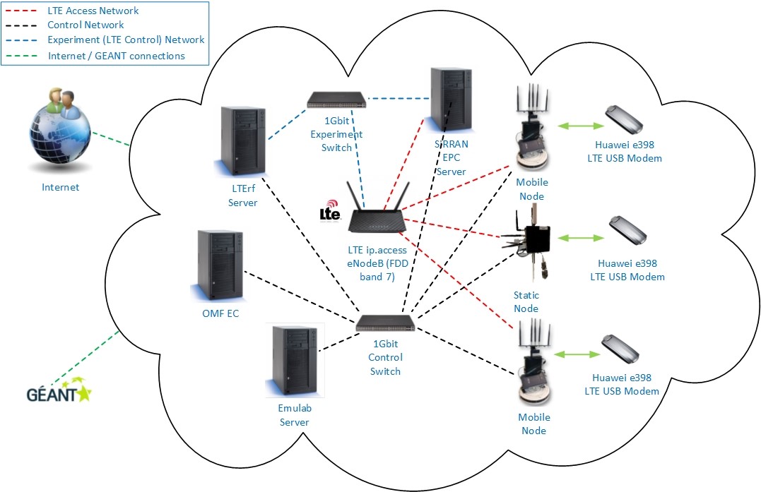
Test frequencies in the licensed LTE band 7, are assigned by the Belgian Institute for Postal services and Telecommunications (BIPT), to be used for experimental purposes. Hence, both femtocells are configured to operate in that band.
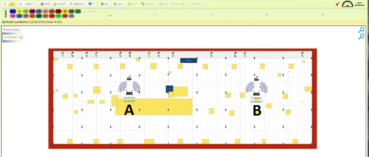
| Possition | Femtocell ID | IP Address |
|---|---|---|
| A | Node 1 | 192.168.1.10 |
| B | Node 2 | 192.168.1.11 |
The following figure depicts the current femtocells deployment in the W.iLab.t testbed at Zwijnaarde.
All the 20 mobile nodes of the testbed are equipped with a Huawei e398 LTE USB modem. Moreover, 8 static nodes, which are distributed in the testbed, are equipped with the same dongles. More information about the LTE enabled nodes can be found in the “Huawei E398u1 LTE USB Dongle UE” section. The ip.access femtocells are connected through the EPC server via a 1Gbit experiment switch. Via the same switch the LTErf server can communicate with the EPC server as well as with the femtocells in order to acknowledge their parameters and configure them respectively.
The experiment interfaces have been configured by default to use the following IP addresses:
- SiRRAN EPC: 192.168.1.1
- LTErf: 192.168.1.2
- Femtocell 1: 192.168.1.10
- Femtocell 2: 192.168.1.11
Through the 1Gbit Control Switch the Emulab server, the nodes (static and mobile), the SiRRAN EPC server, the LTErf server as well as the OMF EC (Experiment Controller) can communicate between each other, using the control interfaces (eth0).
During the experiment definition for each Femtocell the “A Fake OSDI for a fake node representing a device” image must be used.
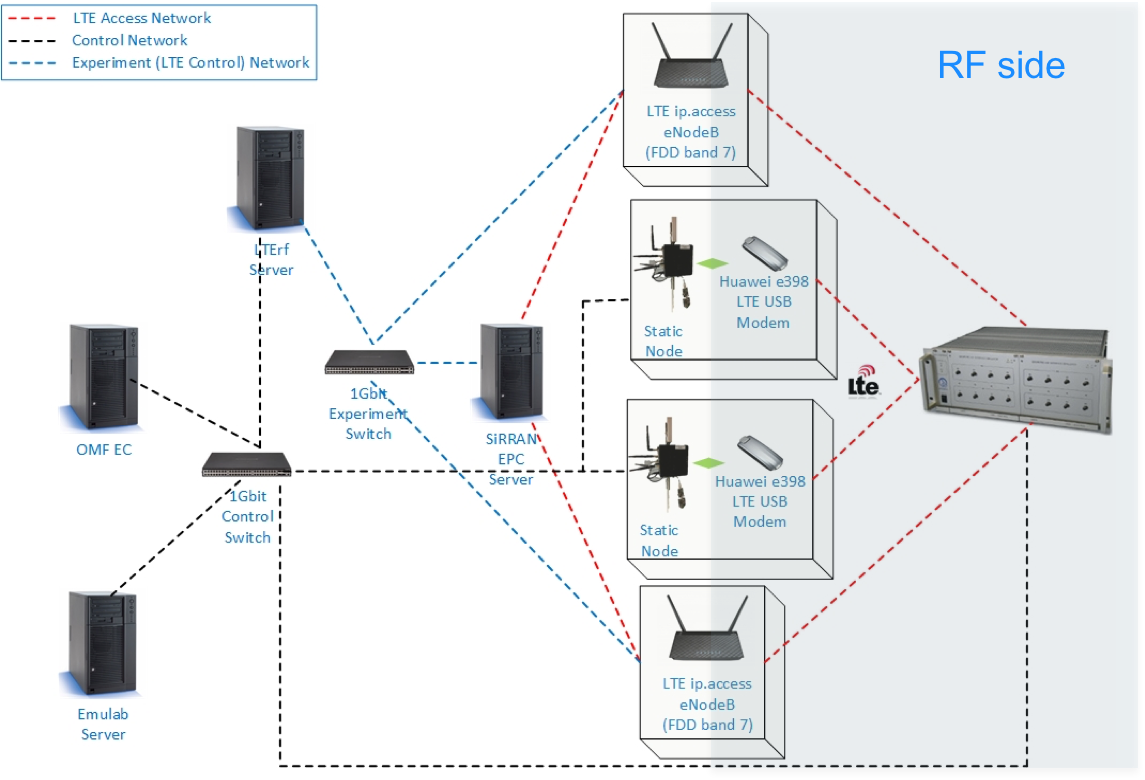
Qosmotec LTE deployment
The following picture depicts the LTE network’s architecture
The experiment interfaces have been configured by default to use the following IP addresses.
- SiRRAN EPC: 192.168.1.1
- LTErf: 192.168.1.2
- Femtocell 3: 192.168.1.12
- Femtocell 4: 192.168.1.13
The SiRRAN EPC must be used with a dedicated server on the Wall1 that has the required license. The name of the server is n073-23a.
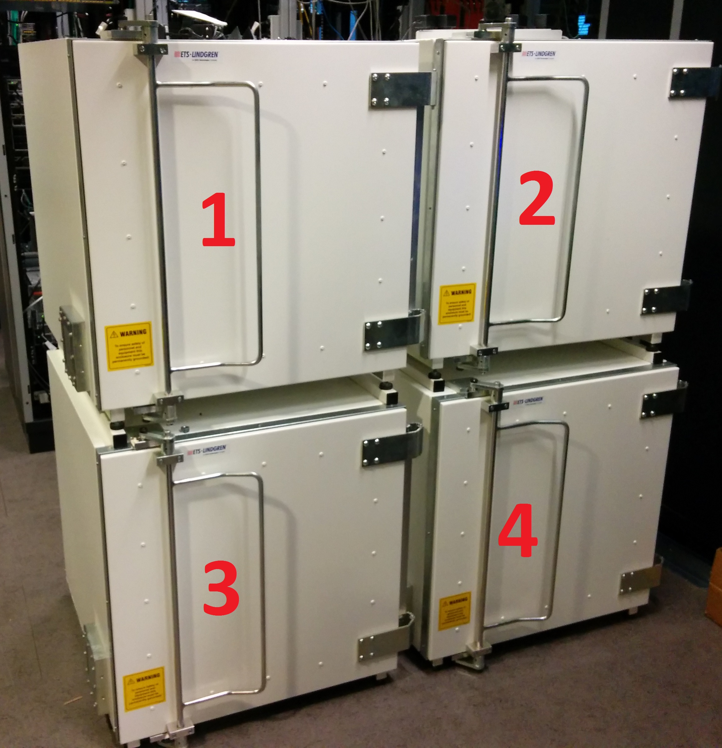
The following picture illustrates the ID of each shielded box.
The table below shows the location of each LTE equipment, their mapping on physical resources and the IPs of their experiment interface.
| Type of Equipment | Resource mapping | Location | IP Address |
|---|---|---|---|
| Femtocell 3 | switch1-13-46 | Shielded Box 3 | 192.168.1.12 |
| Femtocell 4 | switch1-13-47 | Shielded Box 4 | 192.168.1.13 |
| UE 1 | Zotac SB3 | Shielded Box 1 | Specified by the user |
| UE 2 | Zotac SB4 | Shielded Box 2 | Specified by the user |
| EPC | n073-23a | Wall 1 | 192.168.1.1 |
During the experiment definition for each Femtocell the “A Fake OSDI for a fake node representing a device” image must be used.
Qosmotec via webgui
Qosmotec via OMF
An OMF5.4 resource controller is available for configuring the Qosmotec attenuators directly. It runs on the VMWare cluster:
- qosmotec-rc.test
- ip: 10.10.10.135
- OS: Ubuntu 14.04 LTS
- maincomm.py: the class that connects to the Qosmotec attenuators
- qosmotec_att.py: the main program
To run the script type: python /opt/qosmotecrc/qosmotec_att.py
To run an OMF experiment that controls the Qosmotec attenuators, the Qosmotec resource controller should be used. An example ruby experiment file is the following:
######### VARIABLES ############

qosmotec_scripts_dir = '/opt/qosmotecrc/'


defApplication('qosmotec:communicator:app','Control the Qosmotec attenuators') do |app|
        app.description = 'Control the Qosmotec attenuators'
        app.path = qosmotec_scripts_dir + '/qosmotec_att.py'
        app.defProperty('nodeid', "OML node id", "--omlnodeid", {:type => :string, :dynamic => false})
        app.defProperty('exp', "OML node id", "--omlexp", {:type => :string, :dynamic => false})
end

defGroup('qosmotec:communicator:group',"qosmotec-rc.test") do |node|
        node.addApplication('qosmotec:communicator:app', { :id => 'qc'}) do |app|
        app.setProperty('exp', Experiment.ID)
        end
end


onEvent(:ALL_UP_AND_INSTALLED) do |event|
  allGroups.startApplications

  wait 1
  info ""
  info "Connecting to attenuator"
  info ""

  group('qosmotec:communicator:group').sendMessage('qc',
    'connect'
  )

  wait 5

  info ""
  info "Set attenuation on port 1 to 20"
  info ""

  group('qosmotec:communicator:group').sendMessage('qc',
    'attenuate 1 20'
  )
  wait 5

  info ""
  info "Set attenuation on port 1 to 30"
  info ""

  group('qosmotec:communicator:group').sendMessage('qc',
    'attenuate 1 30'
  )
  wait 5

  info ""
  info "Set attenuation on port 1 to 40"
  info ""

  group('qosmotec:communicator:group').sendMessage('qc',
    'attenuate 1 40'
  )

  wait 5
  info ""
  info "Disconnecting and resetting attenuators"
  info ""

  group('qosmotec:communicator:group').sendMessage('qc',
    'disconnect'
  )

  allGroups.stopApplications
  Experiment.done
end