How to program ZYNQ SDR device for bare metal application
This tutorial shows how you can download the bitstream and firmware for bare metal applicaiton on zc706 ZYNQ SDR.
You should have a working SDK project for the board, if this is not the case, you may download
expproj_zc706.zip as an example project for the zc706 board to continue.
If you are using the ZED board (ZEDzynqSDR node in the testbed), you need to have a project that works on the ZED board. Secondly, please replace the server16 and zc706syncsdr1 by the server and zedzynqsdr that you reserved in the testbed.
The following sections shows how to program a zc706zynqsdr, which mostly also apply to the zedboard, however, there are minor differences, please pay attention.
Reservation and jFed experiment
- Reserve a zc706 board and its correspondng host machine from the inventory webpage. To see which boards are available, please refer to Hardware Info ZYNQ SDR.
- Define a jFed experiment, simply select the reserved node.
- If your application needs Ethernet connection with the host, then draw a link between the two nodes, assign desired IP address on both host side and the SDR side.
- If your application does not need Ethernet connection between the board and the host node, then do not draw any link (this is the case for the example project you downloaded)
- Do not specify any image for the nodes, in this case the default image will be used.
- Run the experiment, and wait until all nodes become ready. Ignore the red cross on “Testing connecgtivity to resources on iMinds WiLab 2”, this is normal because ZC706 board is not a standard node in jFed, it does not support all the connectivity tests.
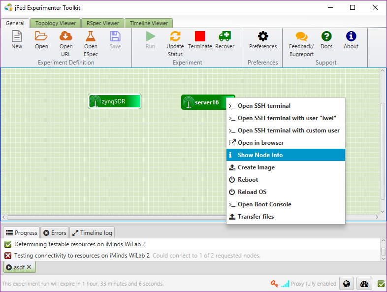
- Double click on the host node (eg
server16) to log in, alternatively, you may right click on the host node and select “Show Node Info” to get the host name, and log in via different ssh client. A screenshot of the running experiment is given below:
Reboot Zynq SDR
Before start programming the SDR, you should power cycle the board by right click on the node representing zynq SDR in jFed experiment, select Reboot, and when the pop up appears, click on Reboot OS.
Establish serial connection
after log into the host node, execute
sudo minicom -s. If minicom doesn’t exist, runsudo apt-get install minicomto install it. Configure minicom as explained belowselect
Serial port setupand typeenter, typeAto edit the com port, usually it is/dev/ttyUSB1for zc706zynqSDR, but it could also others, eg ttyUSB1. For ZEDzynqSDR it is usually/dev/ttyACM0.Please check
/devdirectory to find out what is being recognized. After selecting the serial port, typeentertype
Fto turn off the hardware flow controlfor zc706 board, you may type
enterand exit, this will allow you to communicate with zc706zynqsdr board over serial connection.for zedboard, in addition to steps above, we need to configure the “Modem and dialing” options. Basically, we don’t want Minicom to regard the zedboard serial device as an ordinary modem device. Therefore, we have to clear all modem specific settings. To do so, from the serial port setup, press
Escto go back to main Minicom setup screen and then chooseModem and dialing- In the Modem and Dialing setting, set everything to nothing, starting from option A (Init string) until I (connect string). This will remove unnecessary initialization code that will be sent to the modem when minicom starts.
- Hit
Esckey to exit from the serial port setup menu and you will be back at the base minicom setup menu, select save setup as dfl and hit enter to save the minicom settings as the defaults, than select exit and hit enter to start up minicom with the new settings
Now you should be able to communicate with the boards, if you want to save the serial settings to avoid setting it up, please visit the the Setup minicom in Ubuntu webpage , however please keep in mind that the setting only applies to one jFed experiment, unless you save the image running on the node.
Download bitstream and firmware
Upload the configuration file to the host node uing the following steps * right click on the host node in jFed GUI, and select “Transfer files”, select action “Upload”. * Click on Browse and select “File”, select the zipped sdk folder to upload. Alternatively, you may compress your own sdk project to upload. * Fill in
/tmpas Remote location, and click on “OK”.Open another terminal and log into the server, execute
sudo bashExecute
source /share/xilinx/2016_2/Vivado_Lab/2016.2/settings64.shExtract the uploaded zip file by executing
cd /tmp; unzip /tmp/expproj_zc706.zip, the following files are included in the example project.- hw.bit the fpga bitstream
- sw.elf the compiled firmware
- ps7_init.tcl the initialization script, you should find this file in the hardware folder of sdk project
- debug_nets.ltx this file is optional, it is only for project with debug integrated logical analyzer (ILA) cores
Launch the xilinx lab tool by executing
xsdbExecute
connectto connect to the board, you should see similar printout as below:attempting to launch hw_server ****** Xilinx hw_server v2016.2 **** Build date : Jun 2 2016-16:54:00 ** Copyright 1986-2016 Xilinx, Inc. All Rights Reserved. INFO: hw_server application started INFO: Use Ctrl-C to exit hw_server application INFO: To connect to this hw_server instance use url: TCP:127.0.0.1:3121 tcfchan#0
in the xsdb shell, execute
fpga -file /tmp/expproj_zc706/hw.bitto program the FPGAthe xsdb console prints out progress, such as
100% 6MB 1.7MB/s 00:03, indicates programming completeNext we need to run the firmware on ARM, this is break down into the following steps:
- execute
source /tmp/expproj_zc706/ps7_init.tcl - execute
targets 2to select ARM core 0 as target - execute
stop - execute
ps7_init - execute
ps7_post_config - execute
rst -processorto reset the ARM processor, you should see printout msg:Info: ARM Cortex-A9 MPCore #0 (target 2) Stopped at 0x0 (Vector Catch) - execute
targets 2 - execute
dow /tmp/expproj_zc706/sw.elffile
- execute
after this step, the console should print out similar message such as below:
Downloading Program -- /tmp/expproj_zc706/sw.elf
    section, .text: 0x00100000 - 0x001596e7
    section, .init: 0x001596e8 - 0x001596ff
    section, .fini: 0x00159700 - 0x00159717
    section, .rodata: 0x00159718 - 0x001696e7
    section, .data: 0x001696e8 - 0x0016b1b7
    section, .eh_frame: 0x0016b1b8 - 0x0016b22b
    section, .mmu_tbl: 0x0016c000 - 0x0016ffff
    section, .ARM.exidx: 0x00170000 - 0x00170007
    section, .init_array: 0x00170008 - 0x0017000f
    section, .fini_array: 0x00170010 - 0x00170013
    section, .bss: 0x00200000 - 0x00408117
    section, .heap: 0x00408118 - 0x0840811f
    section, .stack: 0x08408120 - 0x08e0991f
100%    0MB   0.5MB/s  00:00
Setting PC to Program Start Address 0x00100000
Successfully downloaded /tmp/expproj_zc706/sw.elf
execute
conto start running the program, you should observe printout such asInfo: ARM Cortex-A9 MPCore #0 (target 2) Running, observe the serial output in minicom terminal (the first ssh terminal we opened), and observe the serial printout.At this moment, you have succefully configure the ZYNQ SDR’s FPGA and firmware, for the example project, you may wait until
Command loop starts ...is print out, and then execute one of the commands listed in the printout.
Note
On server 16, the board also has Ethernet connection to the server, via interface eno2. If you use Ethernet connection, it is important that you give an ip address to eno2 in a different range than the wilab control backbone network (via eno0), an IP in the range of 192.168.x.x is most safe!
Tip
Sometimes the ZC706 board may crash, if this happens, you can power cycle the board by right click on the zynq SDR node, select Reboot, and when the pop up appears, click on Reboot OS.
Using the Xilinx Integrated Logic Analyzer
If you want to use the ILA (integrated Logic analyzer) of Xilinx for debugging, you also need to upload the probe file to the server. It is usually located in the .run folder of Vivado project, with extention .ltx, in the example project this is the debug_net.ltx file.
- You may open a new terminal on the server, becoming root by executing
sudo bash - Set the environment variable of Xilinx by executing
source /share/xilinx/2016_2/Vivado_Lab/2016.2/settings64.sh - Please note that there is also Vivado 2017.4 installed, in case you need version 2017.4, please execute
source /share/xilinx/Vivado/2017.4/settings64.shinstead of the above - Lauch the vivado lab tool by executing
vivado_lab - You should observe the vivado lab tool GUI pops up, the following refers to operation on the GUI
- Click on Open Hardware Manager, Open target, and then auto connect
- Suppose you already programmed the device as indicated in the previous step, simply specify the probe file by clicking on the Specify the probes file and refresh the device in the Trigger Setup window
- Select the .ltx file you have uploaded to the server and click on Refresh
- You should now be able to view the probe names in the Waveform window.
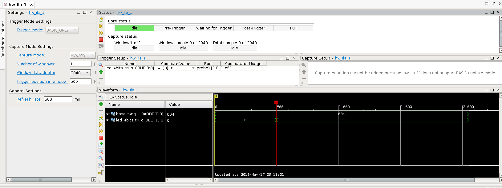
- Feel free to define a trigger condition, and click on trigger button, you can then observe the waveform to debug
- In the example project, a debug probe is inserted on the 4x LED peripheral, you may trigger on the LED port and observe one of the LED pin goes high, as indicated in the following screenshot.