Using the sensor nodes¶
Outdated
Parts of this tutorial are outdated. OMF and OML are no longer maintained. Please contact the testbed owners for more info.
How to program the RM090 sensor node and capture its serial output¶
The most important step is to check if there is a /dev/rm090 device:
/dev/rm090
If the above command doesn’t return anything, enable the USB port on the EE:
/usr/local/bin/sensor_powerctrl/sensor_powerctrl.rb ENABLE
If you want to cut the power to the RM090 again, replace ENABLE by DISABLE.
The scripts for using the RM090 sensor node are located in this directory on the file server (ops):
/share/upload/sensor/
Some applications are located in:
/share/upload/sensor/apps/rm090/
The recommended way to use the sensor nodes in the w-iLab.t testbed is using the OMF framework. Check out the OMF website for some basic tutorials.
An example OMF Experiment description is located here:
/share/upload/omf6/sensor/rm090_test.rb
This script uses the helper script rm090_start.rb to program the sensor node (example RadioPerf code) and start the (TinyOS-specific) SerialForwarder to capture the serial output of the sensor node. Copy the file above to your own user directory and modify the slice and project name before running the experiment. Also make sure that the node names reflect the actual hostname of the nodes in use. For jFed users, the project name will be wall2-ilabt-iminds-be or ch-geni-net, depending on the authority you use. The slice name is the name you chose when starting your jFed experiment.
Run the experiment (on an Experiment Controller) with:
omf_ec -u amqp://labwiki.test.atlantis.ugent.be --oml_uri tcp:am.wilab2.ilabt.iminds.be:3004 rm090_test.rb
After the experiment, the results should be logged in a database that can be queried through the PostgreSQL webinterface. The database should be named the same as your experiment ID (unless you specified the experiment ID yourself). Login credentials are wilabuser/wilabuser .
How to use the Environment Emulator¶
(this tutorial was updated Dec. 2019)
To be able to do power measurements on the RM090 sensor node, the EE needs to be modified. This was only done on a few locations. To find out these locations, check the Wilab2 inventory and use the inventory filter EE_power (=1) (top left).
Load a jFed experiment with the selected nodes. Then run the commands below to start the power measurements. This tutorial assumes that some code is running on the RM090 node. If you use the tutorial below for this (re-route iPerf traffic over Zigbee nodes), then skip the ‘disable USB port’ step in the script below.
git clone https://github.com/WirelessTestbedsAcademy/ExperimentationTools.git
cd ExperimentationTools/EE
Check if the EE device is present (this should be the case when using the default image of the Wilab2 testbed)
ls -la /dev/ee
# if not, find out which device is the EE
motelist
sudo ln -s /dev/ttyUSB1 /dev/ee
Flash the correct EE firmware:
sudo -s
./tos-bsl --invert-reset --swap-reset-test -c /dev/ee -r -e -I -p main.ihex
# if it complains about permissions:
chmod o+x tos-bsl
# if it fails for another reason
killall sf
Run the EE service and keep this running in a separate terminal:
./connectEE
Now you are ready to write commands to the EE. The script write_to_ee.rb can generate EE compatible messages (described in packetlayoutEE.rb) towards the connectEE service. An example of how to use it can be found in the oedl1.sh Before every line with signature “echo….. | ./write_to_ee.rb”, there should be a line that starts with echo to describes every step.
Now run the example scenario that measures the energy consumption. Please have a look at the oedl.sh to investigate the scenario. While running connectEE will dump the samples (voltage and current) to plot.dat. In the background gnuplot will make a live graph of the samples. After the scenario you need to hit <enter> to stop the oedl.sh and gnuplot.
# first install GNUplot if it is not installed
apt-get update ; apt-get install gnuplot gnuplot-x11
# now run the script
./oedl.sh
The oedl1.sh script shows an example on how to do battery emulation. Check the EE hardware page for more details.
Howto re-route iPerf traffic over Zigbee nodes¶
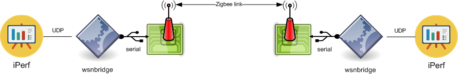
The following tutorial will explain how to set up a bridge over two Zigbee RM090 nodes in the w-iLab.t testbed, over which any UDP traffic can be sent. This tutorial will use a simple iPerf stream to demonstrate.
First off, the architecture of the setup looks like:
Flashing the wsnbridge.ihex to the sensornode is done by (also see REF_HOWTO_SENSORNODE):
/share/upload/sensor/ibcn-f5x-tos-bsl --invert-reset --swap-reset-test -c /dev/rm090 -r -e -I -5 -p /share/upload/sensor/apps/rm090/wsnbridge/wsnbridge.ihex
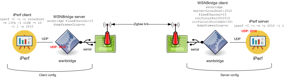
The config of the wsnbridge-app is as follows (for more details, check manpage by executing ./wsnbridge -h):
- Serverside WSN-bridge:
wsnbridge dev=/dev/rm090 fixedChannel=15 dumpFrames2Log=no
(implicitly act as a server and opens up a UDP socket on localhost:2010)
- Clientside WSN-bridge:
wsnbridge dev=/dev/rm090 server=localhost:2010 fixedChannel=15 confLocalPanID=2010 confLocalShortAddr=301 dumpFrames2Log=no
(explicitly act as client, and connect to a serving entity on localhost:2010 to get packets)
This sets up a Zigbee link over the two sensor nodes, and provides an UDP port on both the server and the client side.
To run communication over the channel, use the iPerf-tool:
- Serverside iPerf (run on Clientside WSN-bridge node):
iperf -C -u -s -p 2010 -i 1
(Act as server and listen on port 2010 for connection, the wsnbrige client will dump his packets on this port 2010)
- Clientside iPerf (run on Serviceside WSN-bridge node):
Here we can play with bandwidth settings et cetera. An example is:
iperf -C -u -c localhost -b 135k -l 116B -t 10 -i 1 -p 2010
(start iperf as client and connect to wsnbridge server that listens on localhost:2010)
Overview of the two entities:
Playing with iPerf parameters, you need to follow followling rules:
- Bitrate >= 12B * 8 * 2 = 192: iperf -C -u -c localhost -b 192 -l 12B -t 10 -i 1 -p 2010
- Max MTU is 116B, larger frames will be dropped: keep iPerfs -l flag below 116B
How to setup openwsn development environment for use with Zolertia Z1 and Remote nodes¶
First install all openwsn development environment requirements:
sudo apt-get update
sudo apt-get install -y git
mkdir openwsn
cd ./openwsn/
git clone https://github.com/openwsn-berkeley/openwsn-fw.git
git clone https://github.com/openwsn-berkeley/openwsn-sw.git
git clone https://github.com/openwsn-berkeley/coap.git
cd ./openwsn-fw/
sudo apt-get install -y python-dev
sudo apt-get install -y scons
cd ../openwsn-sw/software/openvisualizer
sudo apt-get install -y python-pip
sudo apt-get install -y python-tk
sudo pip install bottle
sudo pip install PyDispatcher
sudo pip install intelhex
sudo pip install Sphinx
sudo pip install netifaces
sudo pip install yappi
sudo pip install pyzmq
sudo pip install openwsn-coap
sudo pip install PySerial
sudo apt-get install -y gcc-arm-none-eabi
sudo apt-get install -y gcc-msp430
The above commands should have setup the development environment of openwsn. In order to test if all is ok we shall try to compile the node firmware for opensim (the simulator of openwsn) and execute a simple simulation. Firstly we need to compile the node firmware for opensim by defining the platform as python. Follow these steps to setup a simulation:
cd openwsn/openwsn-fw
scons board=python toolchain=gcc oos_openwsn
cd ..
If all is ok the ouput of the build operation should exist in the build/python directory created. And finally start the simulation:
cd openwsn-sw/software/openvisualizer
sudo scons runweb --sim
Once the simulator is booted, a browser can be launched to open 127.0.0.1:8080 , where you can see the openWSN web interface. Inside the ssh terminal you can launch a browser by simple executing “firefox” . If it is not installed,. install it with “sudo apt_get install firefox” first. If you are able to see the openwsn web interface then your environment is sane and you can continue on using openwsn for other platforms like Z1 or Zolertia according to the official openwsn HowTo’s and tutorials.
Making use of SDR in Contiki/TAISC¶
To be able to run TAISC on your ZYNQ SDR in w-ilab.t, please follow these steps.
- Swap in an experiment in JFed with and SDR and the server connected to the SDR: ZEDzynqSDR1 (connected to server9) or ZEDzynqSDR2 (connected to server12).
- Install the Xilinx SDK (2016.4):
- Follow this link and download the SDK: https://www.xilinx.com/member/forms/download/xef.html?filename=Xilinx_SDK_2016.4_0124_1_Lin64.bin
- Transfer the SDK file to the server:
- Right click on the server in the jFed GUI, and select “Transfer filesâ€, and select the “Upload†action.
- Click on Browse and select “Fileâ€, select the SDK installer file.
- Save the installer file in /tmp.
- Log in to the server connected to the SDR
- Change the working directory to /tmp
- Install the Xilinx SDK:
chmod u+x  Xilinx_SDK_2018.2_0614_1954_Lin64.bin
./Xilinx_SDK_2018.2_0614_1954_Lin64.bin

# Now follow the install instructions on the GUI
- Install Contiki and TAISC on the device:
- Clone the Contiki operating system source code and initialize the submodules:
git clone https://github.com/WirelessTestbedsAcademy/contiki.git
cd cont    iki
git submodule update --init --recursive
cd core/net/mac/taisc
git checkout master
cd -
- Install some environmentals. In order to make this permanent, put it in your ~/.bashrc script:
export LLVM_HOME=/usr/lib/llvm-3.6
export LD_LIBRARY_PATH=$LLVM_HOME/lib
export PATH=<SDK_DIRECTORY>/2016.4/gnu/aarch32/lin/gcc-arm-none-eabi/bin:$PATH
export PATH=<SDK_DIRECTORY>/2016.4/bin/:$PATH
- Install dependencies:
sudo apt-get update
sudo apt-get install tinyos-tools
sudo apt-get install libclang-3.6 clang-3.6 -y
sudo apt-get install zlib1g-dev libncurses5-dev -y
sudo apt install python3-pip
sudo add-apt-repository ppa:ubuntu-toolchain-r/test
sudo apt-get update
sudo apt-get install gcc-4.9
sudo apt-get upgrade libstdc++6
pip3 install crc16 sealang
- Now you are ready to compile your first example. For any further documentation on how to use Contiki, please refer to the Contiki documentation.
cd examples/hello-world/
make TARGET=sdr hello-world